Update: We have successfully communicated with the amateur radio transponder QO-100 onboard Es’Hail2. Details on our setup can be found in this post.
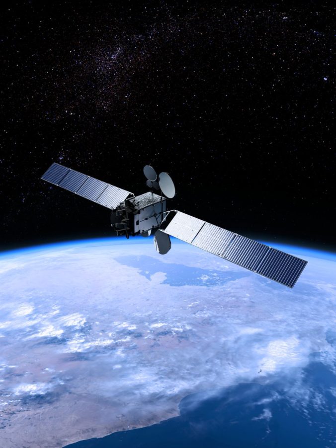
With the successful launch of Es’Hail 2 a couple of weeks ago, we think it is time to talk about our plans for making QSOs on this magnificent bird. Es’Hail 2 is the first Geostationary satellite to carry an amateur radio transponder. At ARK we are eager to explore the possibilities of such a satellite, which promises near constant availability from the areas of the world that are lucky enough to be within its coverage. The fact that Norway shows up on the coverage map, makes us a bunch of happy hams. 🙂
The satellite is set to work with an uplink on 2.4 GHz, and a downlink on 10.5 GHz. In order to make contacts, gain on the order of a 1-2 m diameter parabolic dish, and an uplink amplifier that delivers 10 W are required.
To get started we decided that we would rapidly prototype the setup using equipment we already have, and also simplify things by keeping the RX and TX chains separate. Since the satellite has yet to be commissioned, we figure it will be smarter to start on the RX chain. This way we are able to get some feedback on our solution by latching onto the housekeeping data from the satellite, while waiting for the main amateur transponder to be turned on.
Like many others have suggested before us, we will use a commercial Low Noise Block downconverter (LNB) to go from the RX frequency of approximately 10.5 GHz down to a more manageable Intermediate Frequency (IF). At the IF, we plan to use a USRP N210 SDR to do the final reception. We were lucky to get this donated a while back.
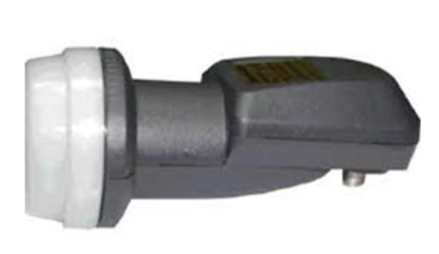
Avenger LNB. Credit: SatelliteBG.com
On the TX side we have a 2.4 GHz 10 W amp from Kuhne. We plan to use this alongside our second USRP N210, and a hack-and-slashed driver amplifier that we will get back to in a later blogpost.
For now we have done some rough measurements on the LNB we bought, to make sure that it will be able to convert successfully. 10.5 GHz is slightly below what the spec sheet says it is able to handle, which is 10.7 GHz to 11.7 GHz RF on the low frequency setting. The LNB uses a fixed 9.75 GHz Local Oscillator (LO) frequency, so if we are able to get it to churn out an IF on 750 MHz and below with reasonable amplitude, the LNB should be usable for working Es’Hail2.
In order to get the LNB responsive, we also had to cook up a small bias-tee – since the LNB takes power over its coaxial connector.
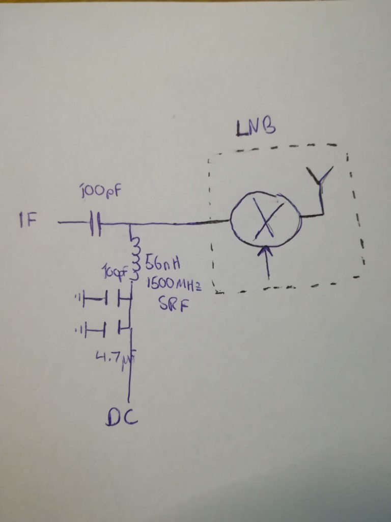
Bias-tee schematic diagram.
The bias-tee is quite straight forward – from our box of capacitors we found a pair of 100 pF in C0G/NP0 dielectric (these behave more nicely when RF passes through them). Additionally we added a 4.7 µF (sufficiently large) capacitor to shunt strays at lower frequencies. For the inductor we opened an inductor kit, and found one that had a Self Resonant Frequency (SRF) above our target IF (approximately 500 MHz to 1300 MHz).
Our method for testing that the LNB would convert “out-of-band” was to boot up our sweep generator and spectrum analyzer. We set up a sweep from 10.2 GHz to 11 GHz, and “listened” in using our LNB, newly made bias-tee and spectrum analyzer. The resulting output on the spectrum analyzer can be seen below.
-
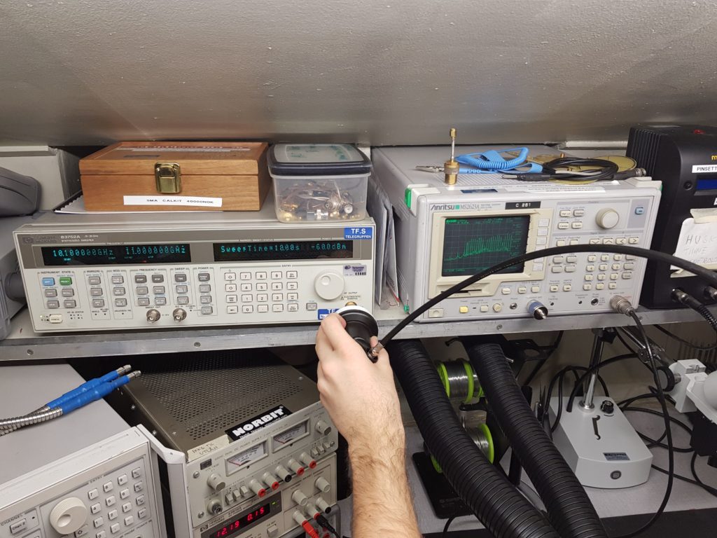
- Rough LNB measurement in progress. Credit: LA1BFA

-
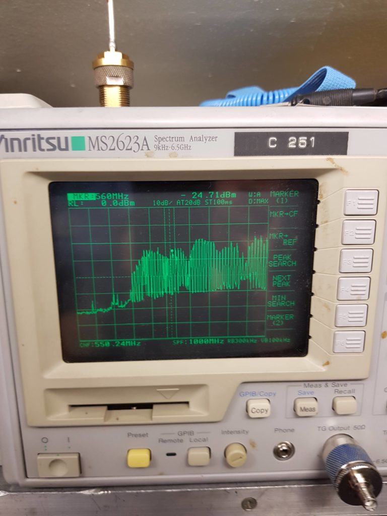
- Output seen from 350 MHz to 1050 MHz. Credit: LA1BFA

The ripple in the spectrum analyzer measurement is likely due to the fact that we did not have a suitable antenna to use on the sweep generator, so the measurement characteristics are heavily impacted by standing waves. Nevertheless, the measurement is successful – as we do indeed get a response all the way down to 300 MHz, with excellent performance at our target of 750 MHz.
Now we need to work on getting the TX side of things ready, while we wait for the satellite to be commissioned. Hopefully we will be ready with our setup to be among the first to work other amateurs. 🙂


0 Comments
2 Pingbacks