On our previous portable trips, we have often used single-band vertical 1/4 wave antennas because of their easy construction and relatively small footprint during transportation. At our trip to Leirsjøen last year, we found that we were too late in setting up our shack, and missed out on the opening for the 20m band. In order to operate the antenna on other bands, the solution was to utilize LA2QUAs automatic ATU to tune our 20m antenna to the 40m band. Although the radiator ultimately was half the desired length, this worked well enough to get quite a few QSOs and further sparked an interest in multi-band portable antennas.
In a recent haul from LA1DI, among other things we received a roll of 450 ohm ladder line, which became the start of this project. Upon doing some research in the field of ladder line antennas, we discovered the “doublet” – a simple dipole fed via ladder line instead of coax. Due to the low loss of the ladder line, even with high SWR, we can make better use of non-resonant antennas for other bands. We still need a tuner since the radio expects a 50 ohm load, but we don’t necessarily need 50 ohm at the antenna side. Dipoles-style antennas are slightly more demanding to erect compared to vertical 1/4 wave antennas because of the requirement of two support points, so we opted for the slightly simpler option: the inverted V dipole-style.
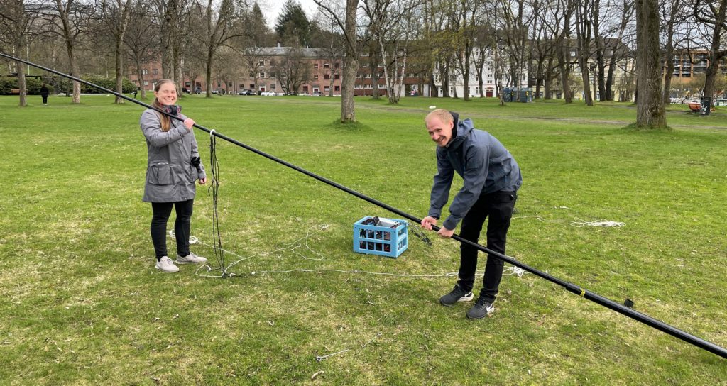
Photo: LB1DJ
We have already written about our previous attempts with inverted V antennas, for example at Munkholmen last summer. One problem with the traditional inverted V-antennas built around our 12m spider beam masts is that the additional weight presented by the balun bends the masts and makes it unstable – as we have previously experienced. Using ladder line allows us to move the possibly heavy balun to the bottom, which can helps to lighten the load on the mast.

Photo: LB5DH
The inverted V antenna shares a lot of the properties from the similar, traditional dipole antenna. One of these properties is the required height above ground, which increases with the wavelength. For portable operations we have a 12 m high Spiderbeam glass fiber mast, which limits the maximum height of our antenna. Because of this, we settled for the 40m as the lowest band.
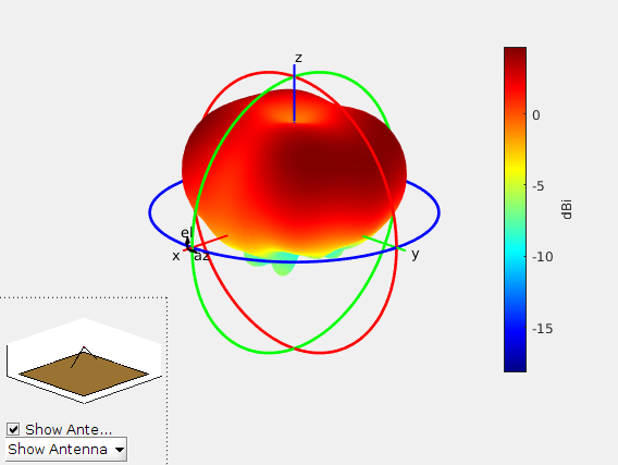
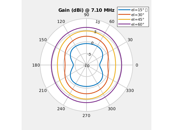
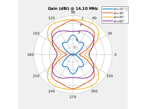
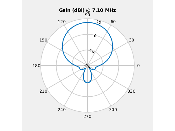
There are two main parameters to vary for an inverted V-antenna – the height of the center point and the angle between the elements. Below are a few plots trying to illustrate these differences. They show an inverted V with approximately 10m long elements, center point 12m above perfect ground and an angle of either 90 deg or 150 deg.
Disclaimer: These plots must not be regarded as accurate representations of the antenna we built, but illustrate the variations from height relative to wavelength and angle between the elements.
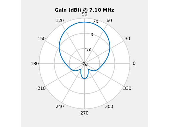

With a 90 degree angle, we can see that this antenna is not ideal for DXing, which benefits from a low take off angle. In particular, for the 40m band, where the antenna is relatively low in height, most of the radiated power is radiated upwards. On the 20m band the take off angle is somewhat lower, approaching 30 degrees.
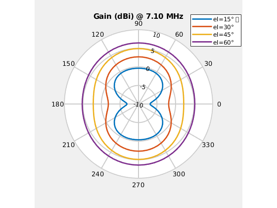
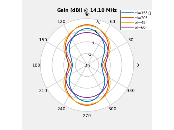
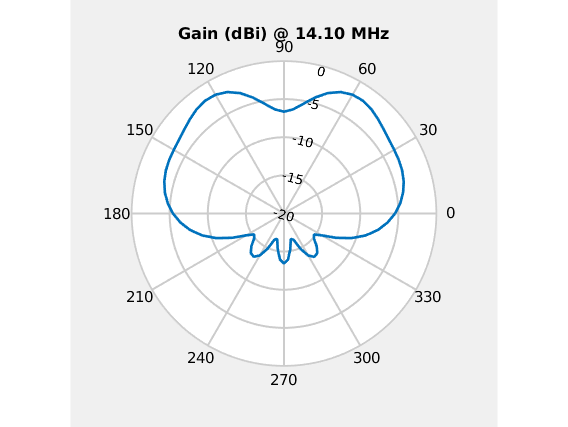
These next plots indicate that the height matters more than the angle, but there are some differences. With a larger angle, the shape and thus the antenna diagram becomes more dipole-like. The 40m band however still suffers from the low overall height, while the 20m band has more gain in the azimuth direction.
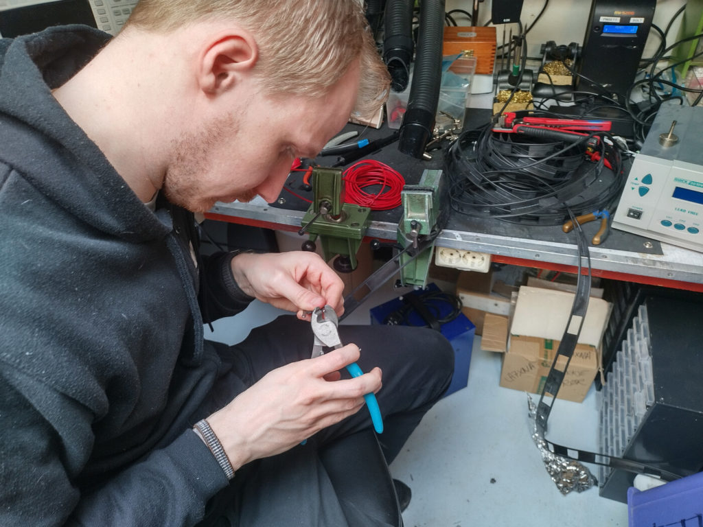
Photo: LB5DH
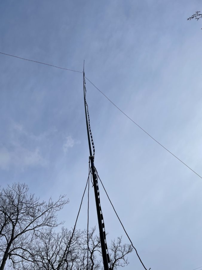
On Sunday we got together to assemble the antenna and started out with the ladder line on the workbench. On the antenna end we soldered on the elements cut as a 40m dipole, plus an additional 3.5% length. On the other end we attached cable shoes, so that we could attach the antenna to our Heathkit tuner. To maintain the load presented at the top, we added a strain relief at the top made from a plastic insulator and some cable ties.
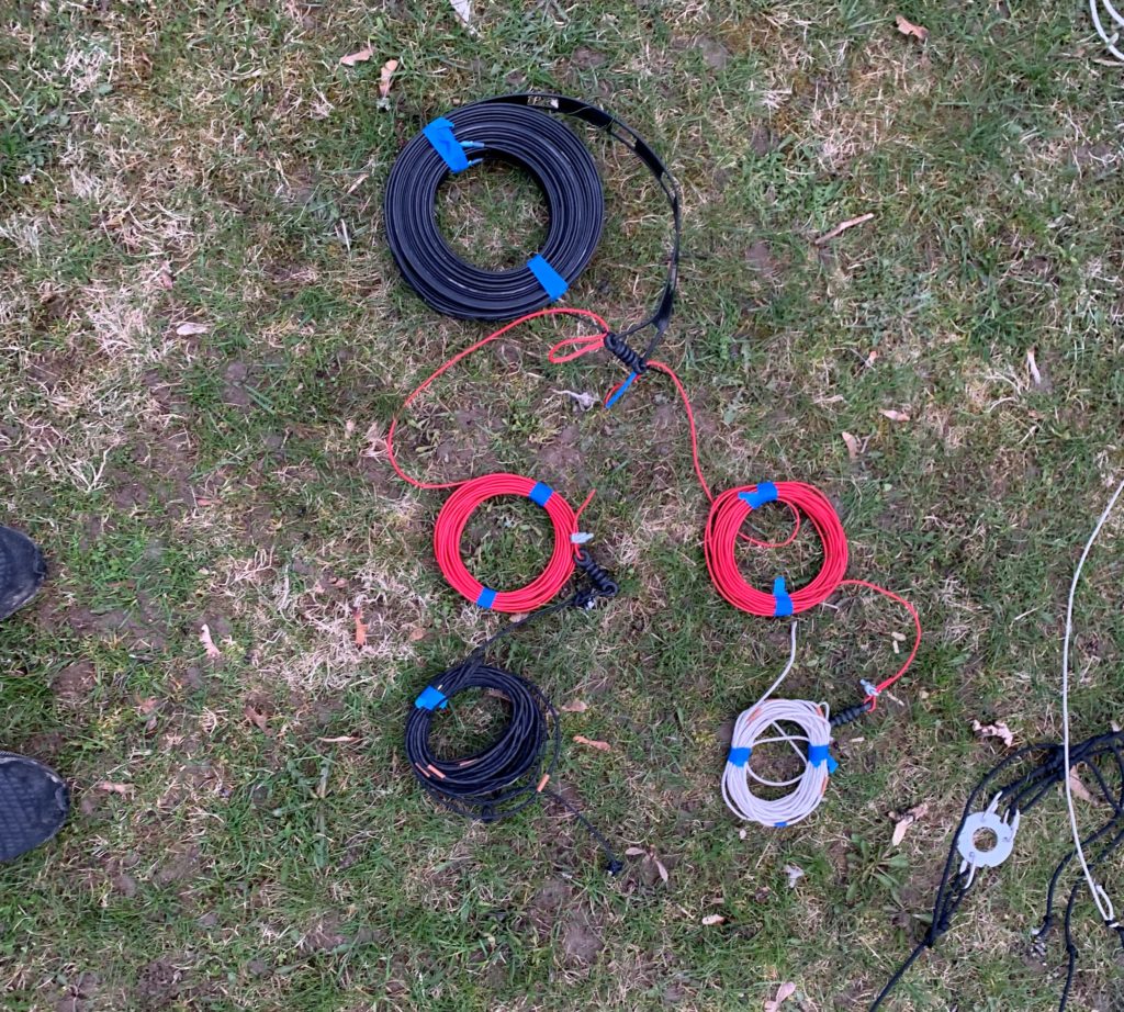
Photo: LB8LI
When the antenna was completed, we went outside to test it in the park. After mounting the center piece and erecting the mast, we connected it up and started the tuning process and after a while got it to tune on the 40m band. It is difficult to assess how well it worked, but after hearing several stations on the band and getting one QSO we deemed it a success.
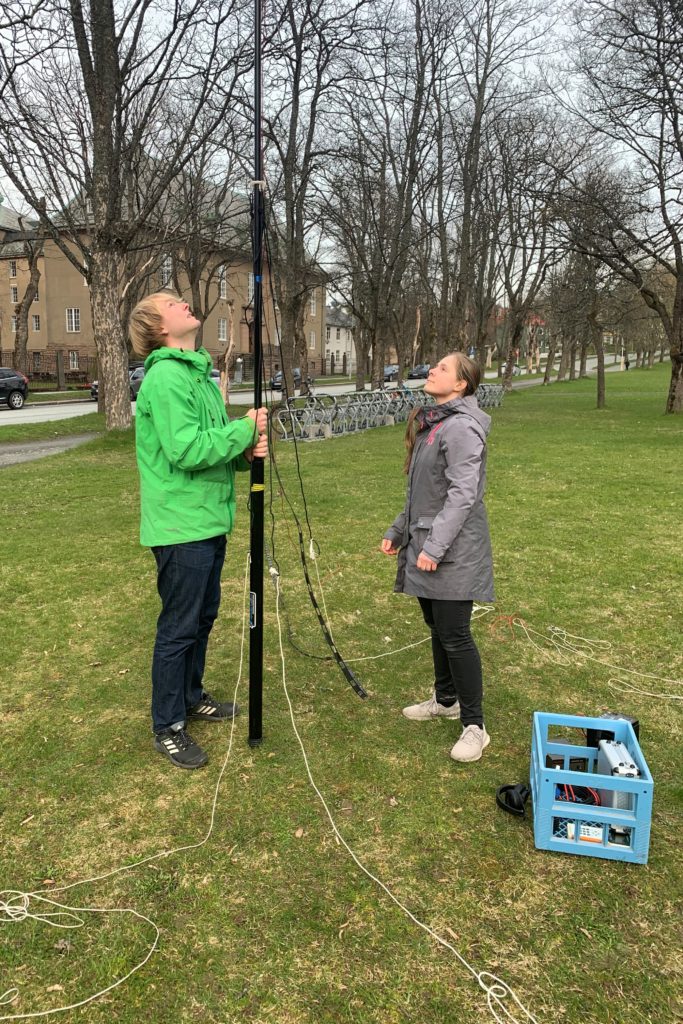
Photo: LB8LI
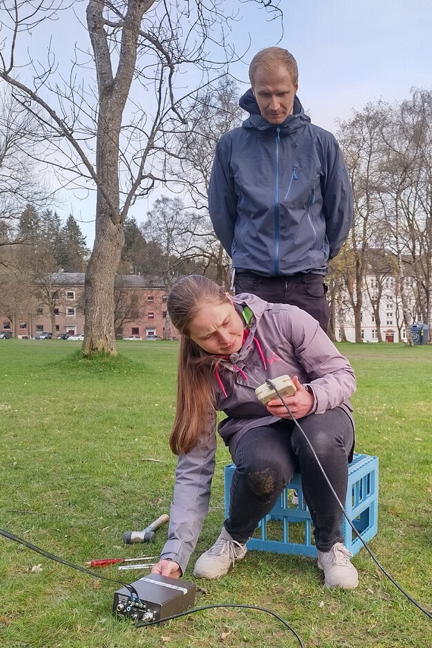
Photo: LB5DH
Although we successfully tested the new antenna with our Heathkit manual tuner, we also wanted to test it with our newly acquired LDG Z-11 Pro-II autotuner. Since the new LDG tuner was unavailable on Sunday, we decided to meet up on Tuesday to try again. One difference between our old manual tuner and the autotuner is that the former has a balanced output to attach the ladder line to, while the latter only had a unbalanced antenna-output. We got around this by using a 4:1 balun and a self made adaptor for attaching the ladder line.
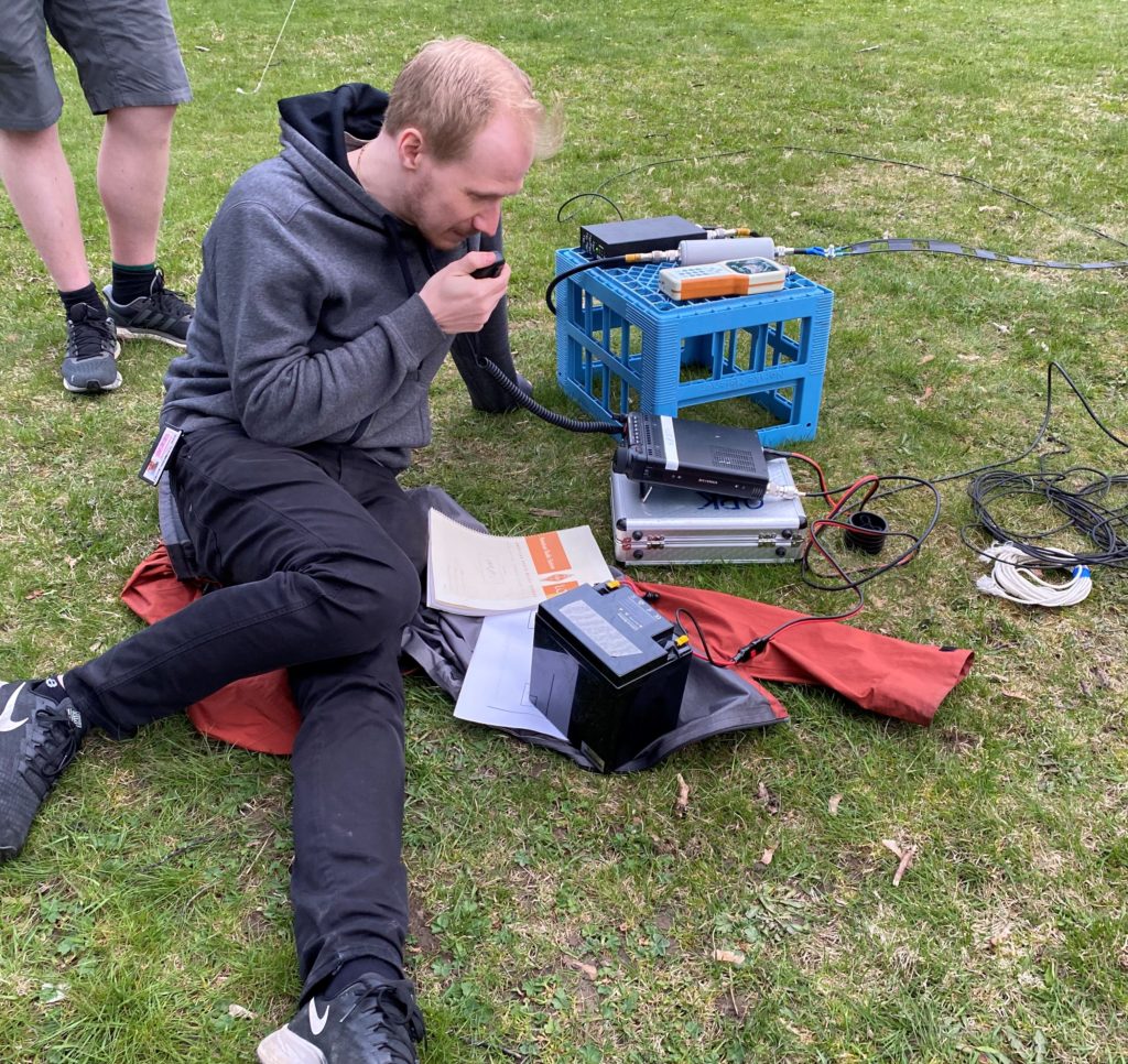
Photo: LB9WI
After once again erecting the antenna we found the autotuner performed very well and achieved a lower SWR compared to the manual tuner we had used earlier. We managed to get QSOs on both the 40m and 20m bands, but not on any of the lower bands. The tuner also proved capable of tuning the antenna all the way up to 6m, but because of poor conditions we found no other stations on the band.

From the back: LB1DJ, LB8LI and LB5DH
Photo: LB9WI
All in all, we have high hopes for further use of this muti-band antenna, and will definitely keep it in our inventory of available portable-antennas. Albeit not very capable of DX, it proved efficient for regional QSOs during our portable trips and thus will complement the low take off angle from the verticals we often use. Many thanks to all participants and LA1DI for the ladder line and balun we used in the project!


0 Comments
4 Pingbacks