We have been looking for a horizontally polarized omnidirectional antenna that could be used on a future 23 cm beacon. While a perfectly omnidirectional antenna would be best we are able to cope with some nulls in the antenna-pattern. A quick and easy antenna that does this is a half-wave dipole, which is largely omnidirectional, but may have some nulls at certain elevations.
The half-wave dipole has a feed impedance of around 72 Ohms. To get even better performance the dipole can be matched to 50 Ohms with a balun. We chose to use a quarter wave impedance transformer, which is often called a sleeve or bazooka match. The sleeve also prevents unintentional radiation from the coaxial feed cable.
The rest of this post is a tutorial on how to build the 23 cm sleeve dipole. For outdoors mounting it is made extra waterproof, this adds some additional design considerations.
Required materials:
- 10 cm or longer coaxial cable (we use RG-223 for this guide)
- 20 cm of 6 mm inner diameter 7 mm outer diameter copper tubing. If you use a thicker cable than RG-223 you can use a wider copper tube. This will increase the bandwidth of the antenna but lower the efficiency somewhat.
- 20 cm adhesive lined shrink tubing 5-6 mm shrunk diameter
- 5cm self-amalgamating tape (heat activated)
Required tools:
- Hacksaw
- Cable cutter
- Knife
- Soldering iron
- Heat gun
- Measuring tape or caliper
- SWR-meter or network analyzer covering 23 cm (up to 1300 MHz, preferably higher)
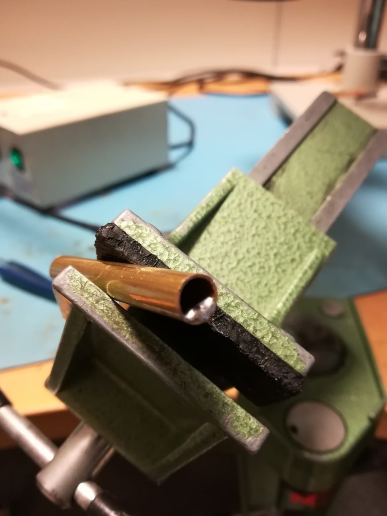
Start by cutting three 55 mm long sections of copper tubing. I used 6 mm inner diameter and 7 mm outer diameter for my copper tubing in order to fit around the cable I decided to use. If you decide to make the antenna for a different frequency the cut length can be calculated roughly as (where f is the frequency in Hz):
-

- Three 55mm long pieces of copper tubing.
-
- A clamp is helpful when cutting the copper tube.
The copper tubing is used for each leg of the dipole, as well as the quarter wavelength sleeve.
The next step is to prepare the coaxial cable. Three cuts should be made, one to remove 5 mm from the end of the jacket, where the dipole legs should be soldered. The two remaining cuts should be made at 55 mm and 60 mm, where the sleeve will be soldered to the coaxial shield.
-
- The RG-223 assembly. Mine was already terminated with an SMA connector.
-
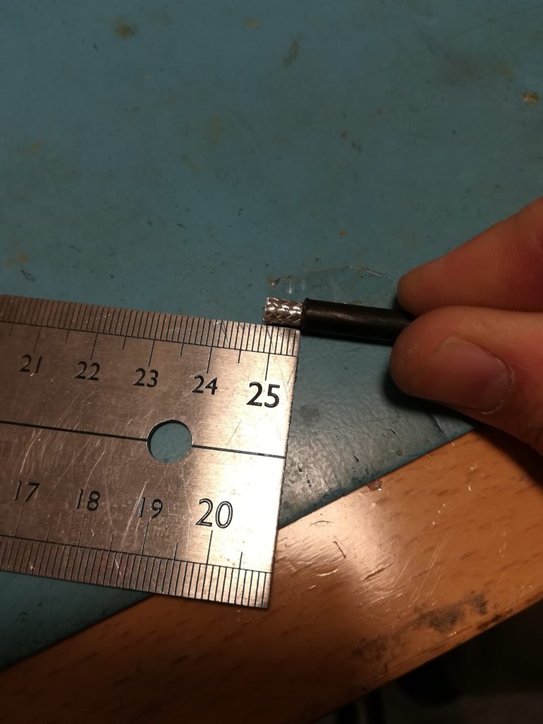
- Remove 5 mm of the jacket where the dipole legs will be soldered.
-
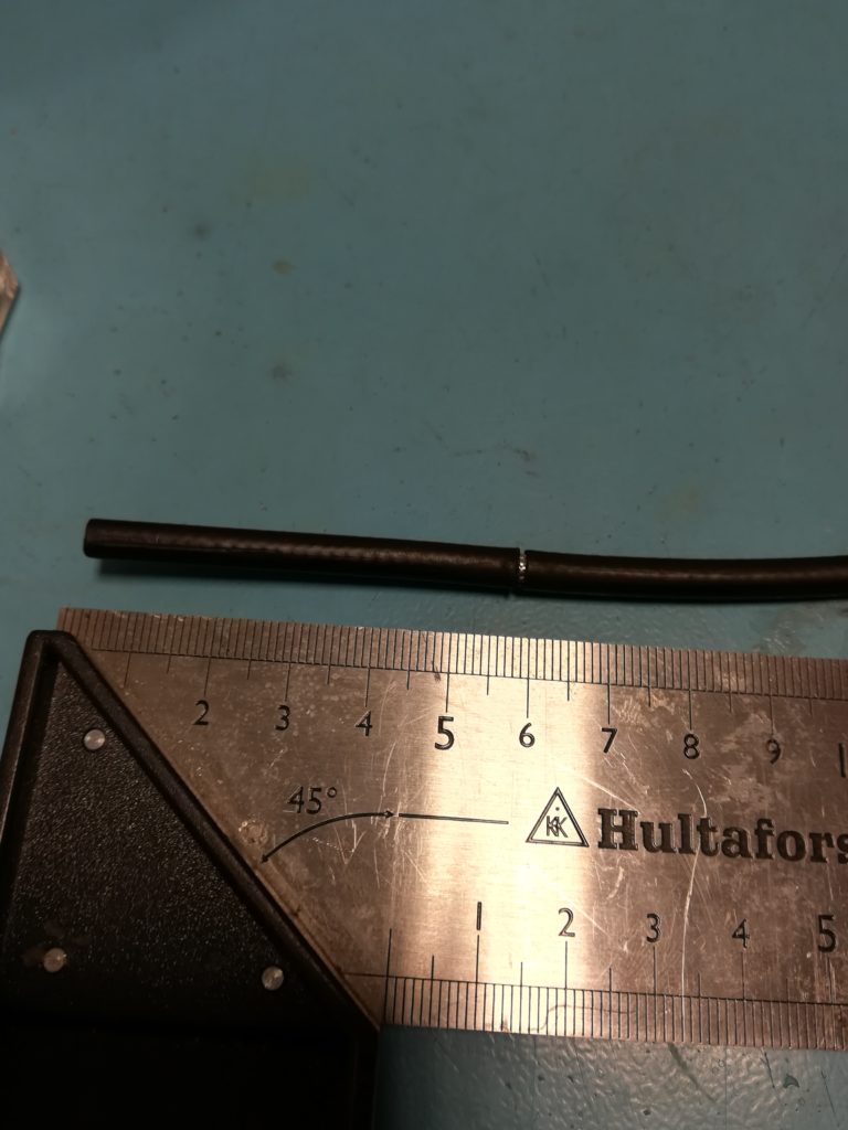
- Make a cut at 55 mm, this is the upper bound for where the sleeve will be soldered to the coaxial cable.
-
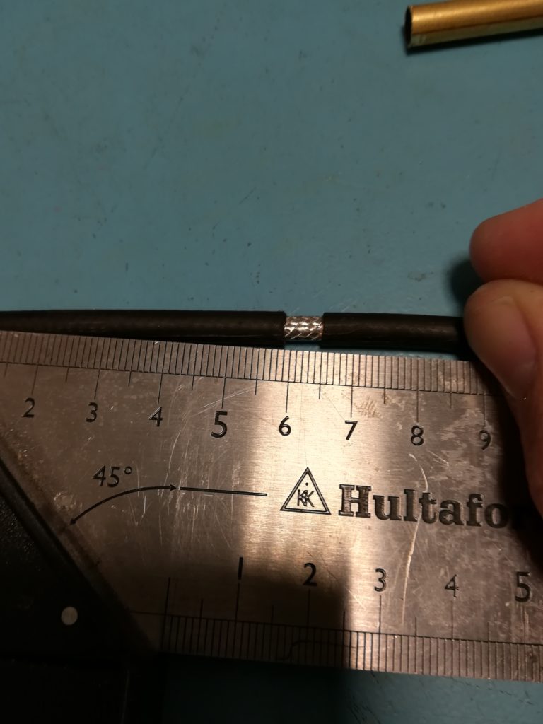
- Make another cut at 60 mm and remove the jacket between the 55 mm cut and the 60 mm cut.
The next step is to prepare the end of the coaxial cable for soldering to the copper tubing. If you are using a coaxial cable that is already terminated you must make sure to thread the sleeve tube and a piece of heat shrink that is 7-10 mm long over the coax before soldering the dipole legs.
-
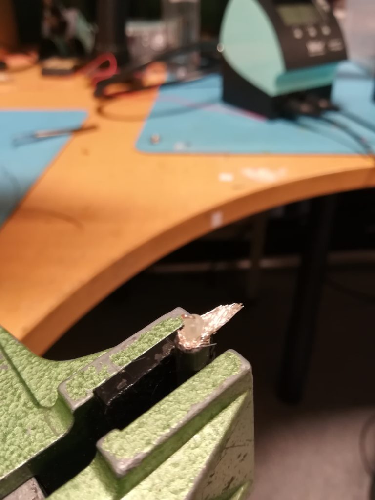
- Unbraid the shield and move it to one side. Remove about 2.5 mm of dielectricum and fix the center conductor to the opposite direction of the shield. Add solder to both shield and center conductor.
-
- Add a reasonable amount of solder inside one end of the copper tubing. Do this on both tubes that make up the dipole legs.
-
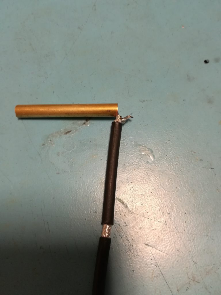
- Solder one leg of the dipole.
-
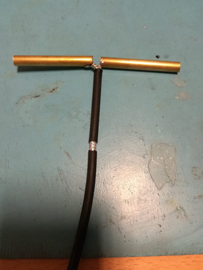
- Both dipole legs attached.
Take extra care to avoid solder bridges between the left and right leg of the dipole, they should be electrically separate. When soldering the sleeve in the next step, make sure to avoid contact between either leg and the open end of the sleeve.
-
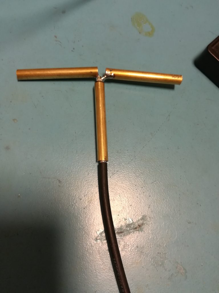
- Move the sleeve up to the opening in the coaxial jacket between 55 mm and 60 mm.
-
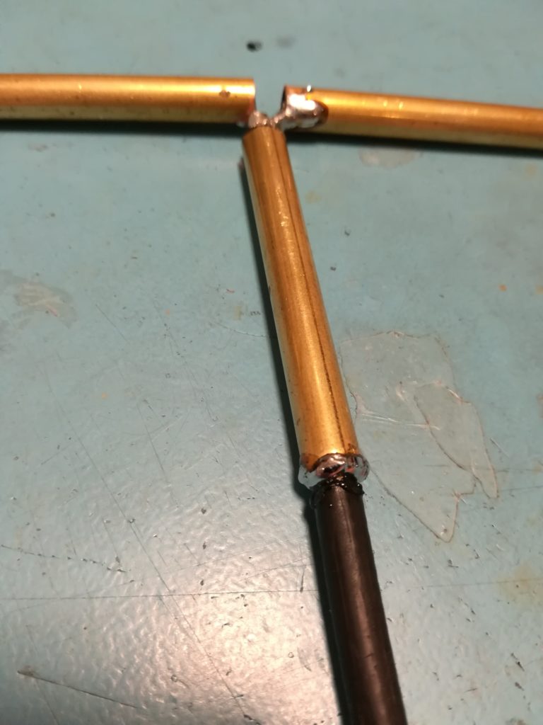
- Solder the jacket to the bottom of copper tubing sleeve. Make sure to avoid short circuiting the open end of the sleeve to the left and right dipole legs.
-
- Move the heat shrink tubing up to the sleeve and apply heat.
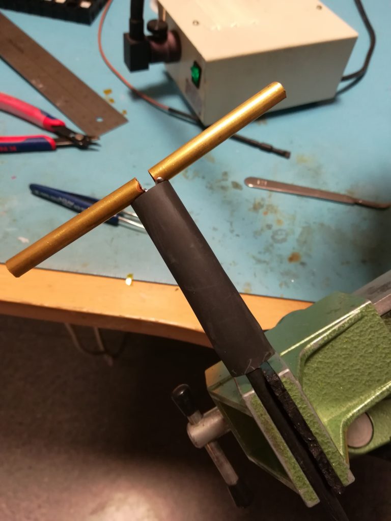
Next up is tuning the resonance. This is done by cutting the dipole legs until the antenna resonates at the desired frequency, for me this is 1296 MHz. One very interesting thing to note when adding heat shrink tubing on the outside of a radiator is that the resonant frequency will shift down. This is due to the increased dielectric constant of the heat shrink plastic compared to air. To mimic this behavior during measurements I place the heat shrink tubing over the copper tubing, but I don’t shrink it until I am satisfied with the resonance. Keeping in mind the dielectric effect, I tune the antenna a little bit too high to compensate for the dielectric constant, which gets a little larger when the plastic is fully shrunken.
-
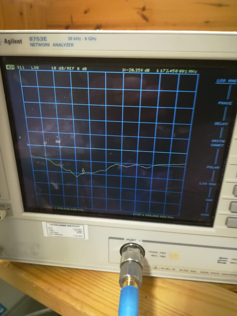
- Initial resonance is approximately -20 dB at 1150 MHz. The dipole must be shortened a bit in order to shif the resonance upwards.
-
- New resonance, -30 dB at 1240 MHz. More shortening is required.
-

- Final resonance, -30 dB at 1350 MHz. A little high, but hopefull the resonance will shift down once heat shrink is shrunken.
-
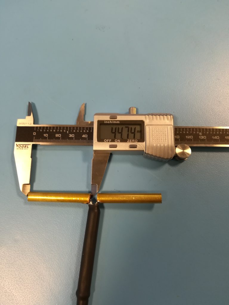
- Final lenght of left leg: 44.74 mm.
-
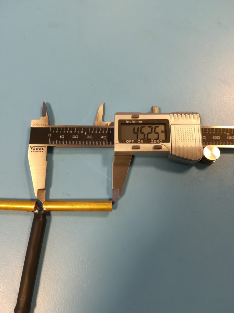
- Final length of right leg: 45.25 mm.
Now all that remains is to add heat shrink to the dipole legs. In order to make it waterproof at the middle and at the ends I use a type of self-amalgamating rubber that melts into a solid mass when heat is applied.
-
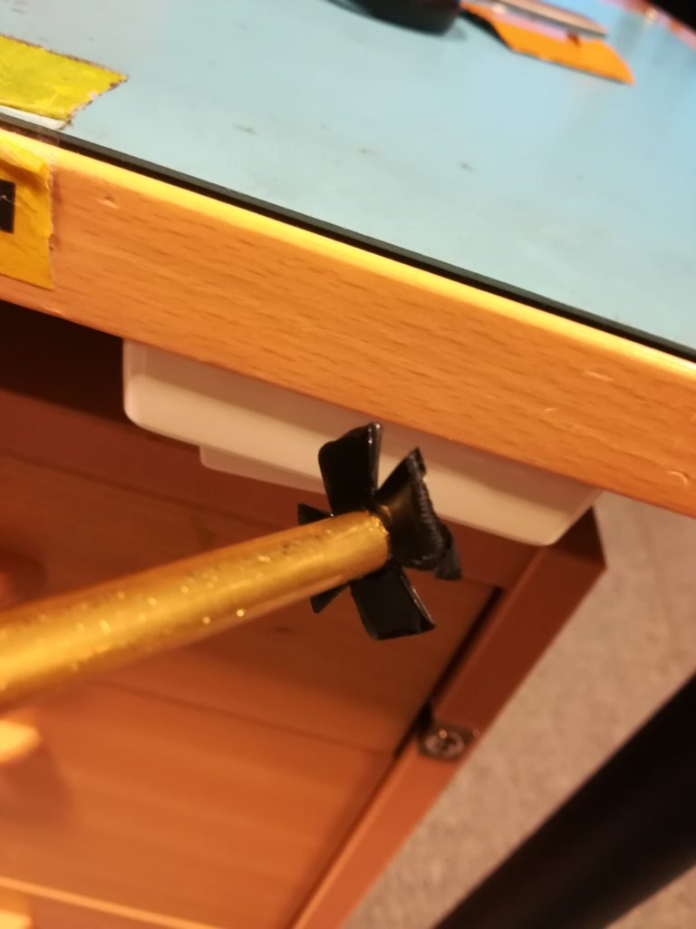
- To keep it tight at the ends a star-shape is cut out of self-amalgamating rubber. This star is folded around the edges.
-
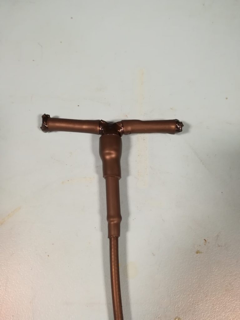
- A waterproof 23 cm sleeve dipole.
-
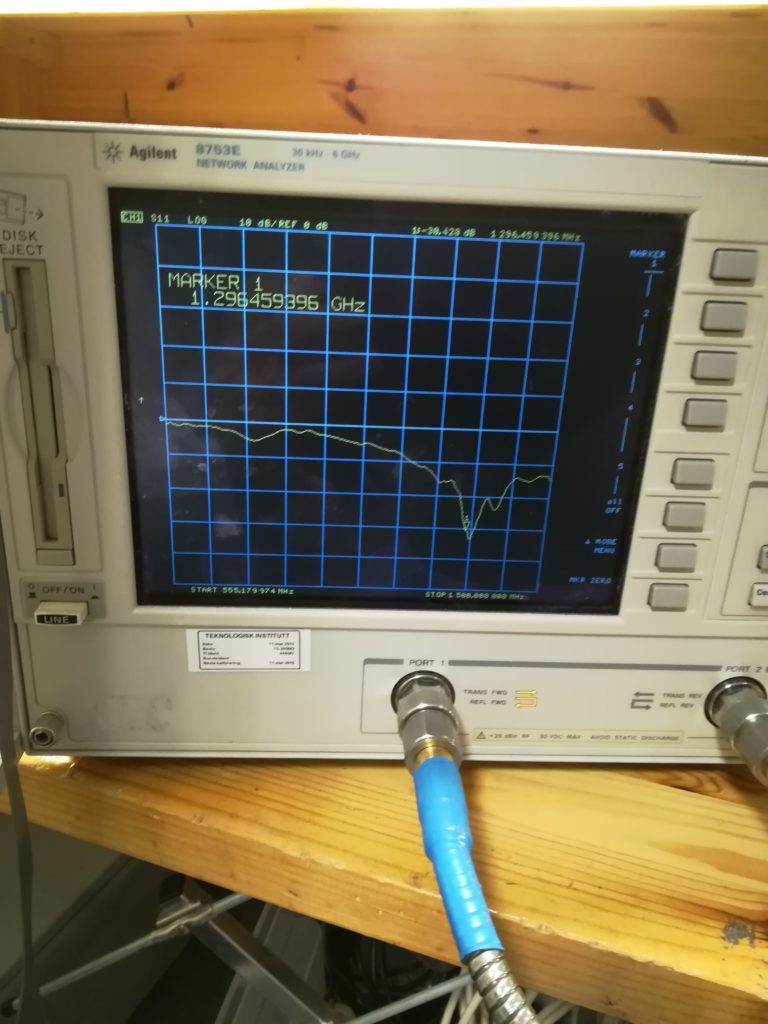
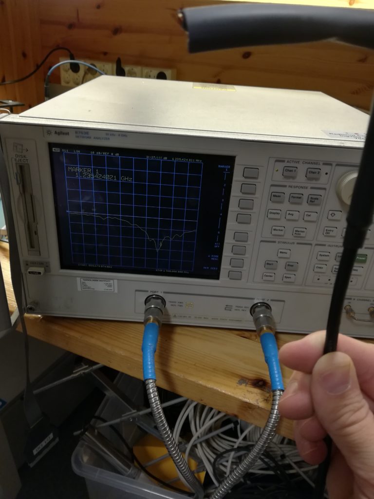
- Measurement showing final match of -30 dB at 1296 MHz, success!
-
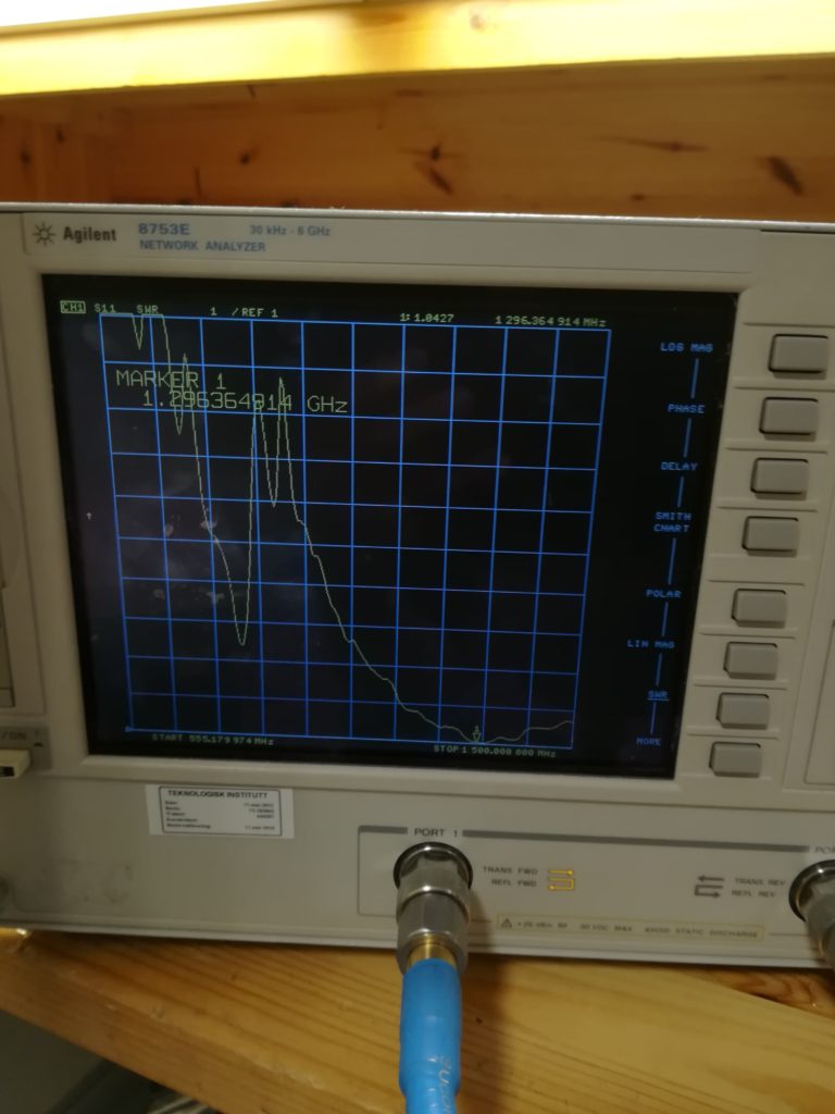
- The same measurement, shown as SWR. The antenna boasts an SWR of 1.04 at 1296 MHz.
The end result is a cheap and simple antenna that performs well. In total the antenna took about one hour to make.

you don’t show when you fitted the inner link wire in the dipole, was that after tuning and before sealing up ?
Hi Rich!
Hope I am understanding your question correctly. There’s no wire support between the two legs of the dipole, it is supported largely by the self-amalgamating tape. We found that the dipole is light enough to be supported this way, as the self-amalgamating tape and shrink sleeves are quite rigid once shrunk.
73 de LA3WUA
ah! – I found your site when I was looking for information on the coaxial dipole which has a wire through the middle of the tubes and joins end-to-end as a coaxial dipole ( like G4CQM 70ele 23cm design I’m rebuilding the driven element of) and can be connected directly to coax without balun or bazooka. Nice to see my beacon spot on your LA2VHF/4m beacon via Es on your site too ! my little bit of fame :-p 73 Rich