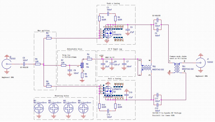
This week we take a look at the AFM907N amplifier in a 10 W push-pull configuration.
We have been eagerly following entries into NXP’s annual design challenge. This year the challenge is based on the MRF101AN (MRF101BN in alternate pinning), which is a 100 W 50 V LDMOS device. What really amazed us this year was the simple, yet incredibly efficient output match utilized in the winning design.
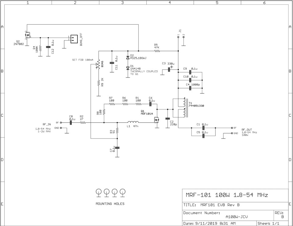
Design winner Jim, WA2EUJ, demonstrates how a cheap and readily available common mode choke can be utilized to both step up the impedance 4:1, and simultaneously choke the DC feed for the amplifier drain connection. His design files can be found at this website. The amazing thing about this use of the common mode choke is that it greatly simplifies amplifier construction. Instead of hand-winding wire on ferrite cores, the output match may now simply be soldered, or even better: pick-and-placed and reflowed, onto the board.
This has got us thinking. Jim’s design steps the output impedance from 12.5 Ohms to 50 Ohms through the 4:1 properties of the common mode choke. Another amplifier that could benefit greatly from this output match is a lower powered device running at a lower drain voltage, as the intrinsic output load will still be in the 10-15 Ohm area (with proper power/voltage ratios).
One of our undisclosed projects would benefit greatly from finding a way to manufacture very many very cheap ~10 W amplifiers, so we set out to find potential candidates.
Some days of intense searching led us to the AFM907N device from NXP. The device is an 8 W LDMOS for ~8 V operation over the frequency range 136-941 MHz with a PAE around 60%. It is attractively priced (1.5$ @ 1k QTY), rugged, and within our desired power range. Its potential usage in the VHF and UHF bands are relatively obvious, but we had the HF band in mind. For that purpose, the most important characteristic is that the device is not internally matched – meaning that we can potentially abuse this device into service in the amateur radio HF bands.
It was time to head to the simulation bench to see if we could force AFM907N into servitude. For the first bringup we used the same Wurth 744851330 common mode choke that Jim uses, and found the following:
- Terrible low frequency oscillations occur if one attempts to use the device without feedback. Standard R+C calms things down to manageable levels.
- Gain is excellent for a wide tuning at “low” frequencies. Allows usage of simple resistive input match, which again improves bandwidth.
- HF Output match improves significantly if the voltage is upped to around 10-12 V, in comparison to the datasheet nominal 7.5 V.
- Devices seem happy in a push-pull configuration. This makes it easier to achieve the power goal (10 W), and also simplifies filter construction down the line (push-pull kills 2nd order harmonics).
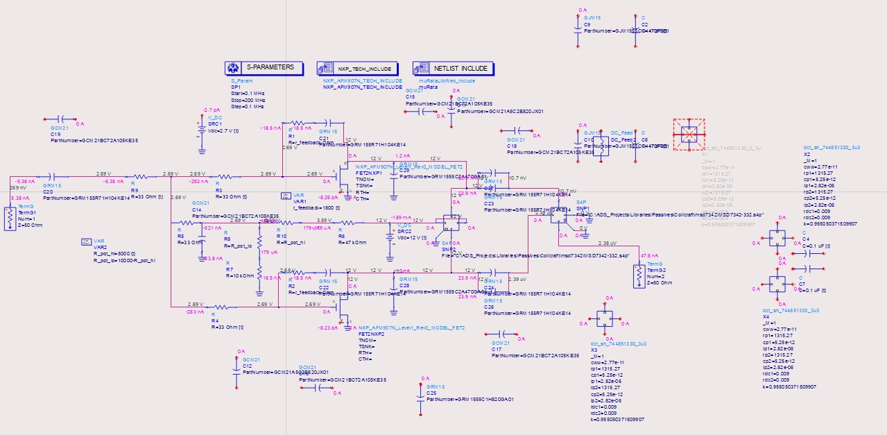
Since the 744851330 choke is quite pricey (4.5$@1k QTY vs 1.5$ for AFM907N) and large, we decided to look for some cheaper alternatives. We think we found a nice substitute in Coilcrafts MSD7342-332. Simulations look decent, so we’re moving on.
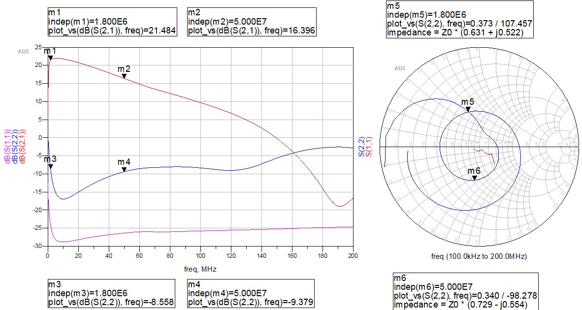
End-of-first-simulation-cycle results show a PA with high, somewhat sloping gain. Sloping gain can be a bit annoying, but since the gain is large enough we are not too worried about compensating for this elsewhere in a hypothetical transceiver.
Typically, amplifiers can end up having quite high output impedances, and still be able to turn around lots of power. The match is good-ish now, but it remains to be seen if this is also able to drive power into a load.
At this stage, the main motivation for moving to a prototype is that it is very hard to simulate saturation effects in the common mode choke with the models that are available. We will probably bring the device back into the simulation bench to optimize further after we get the prototype, but first we need to verify that the simulations yield correct results.
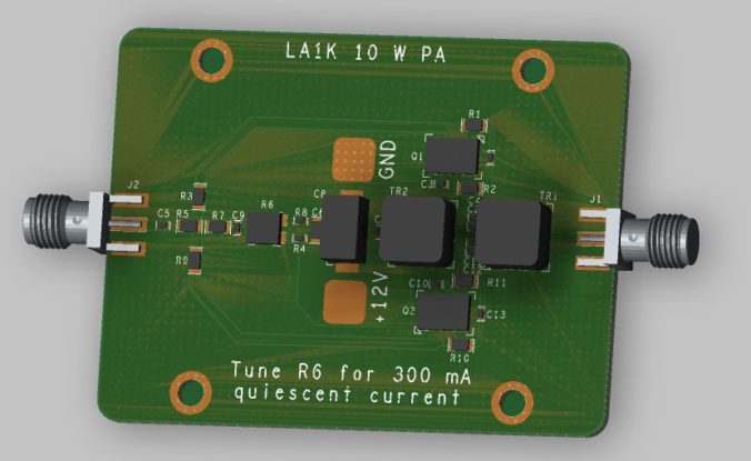
Without considering the cost of SMA connectors and the PCB, it looks like the amplifier can be built with a BoM as low as 8-10$. We will get back to this in more detail once we have tested the amplifier, and released the design files. We added provisions for a simple heatsink, although we’re hoping that the efficiency will be high enough to be cooled by simpler means like sheer PCB mass.

The prototype order has been placed, so now it is time to wait. Fingers are crossed that the simulation results are close to what we will see in the lab.


0 Comments
1 Pingback