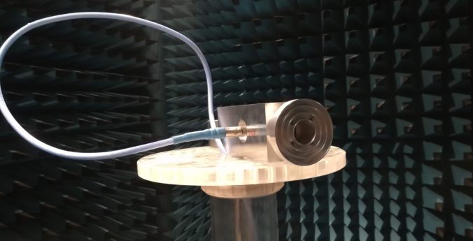
We have bought a 3 cm septum feed from PE1RKI (OM6AA design), which we intend to use to become QRV on 3 cm EME over the course of the next year. To start it all off, we want to share some antenna pattern measurements we did on the feed.

The measurements were done in the local university’s
(NTNU) 4 m anechoic chamber. A ETS-Lindgren model 3117 was used as the reference antenna. We swept the range from 7.5 GHz to 15 GHz in 100 MHz steps in order to identify if the antenna may also be usable outside the amateur band. For brevity, only the measurements that correspond to the amateur radio band at 10.3 GHz is shown here. However, the full measurement data is available on this GitHub repository. These can be visualized using scripts found in this Jupyter notebook (.ipynb file may also be found in the GitHub repository).
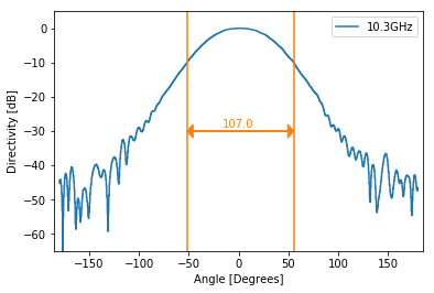
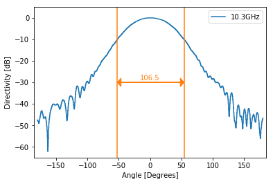
The antenna has two ports, Right Hand Circular (RHC) and Left Hand Circular (LHC). Additionally, the reference antenna is sampled once in the Vertical and once in the Horizontal polarization. This gives a total of 4 datasets. The 10 dB angle is illustrated with orange lines.
Left hand circular port:
Reference Vertical 
Reference: Horizontal 
Wide band 10 dB angle. Reference: Vertical 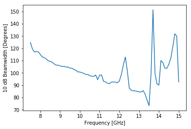
Wide band 10 dB angle. Reference: Horizontal
Right hand circular port:
Reference: Vertical 
Reference: Horizontal 
Wide band 10 dB angle. Reference: Vertical 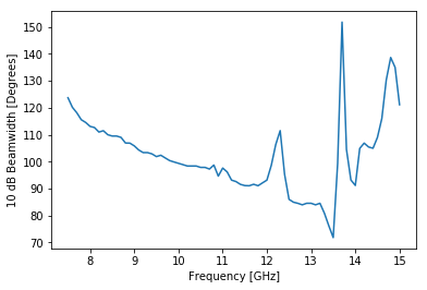
Wide band 10 dB angle. Reference: Horizontal
The feed is to be used with a dish with a f/D of 0.45. This corresponds to an ideal 10 dB beamwidth of 116.2 degrees. It seems to be common to under illuminate the dish slightly, as this helps reduce system noise. The measured 10 dB angle is slightly above 100 degrees, which should be a fair compromise.
In the results, the 10 dB width is different for vertical and horizontal reference positions for the same frequency. Since the zero-level for both reference positions is equal, this indicates that the circularity of the antenna is reduced towards the edges of the 10 dB beamwidth. This is entirely normal, and should not degrade the performance significantly – but quantifying this effect requires a much more elaborate measurement setup.
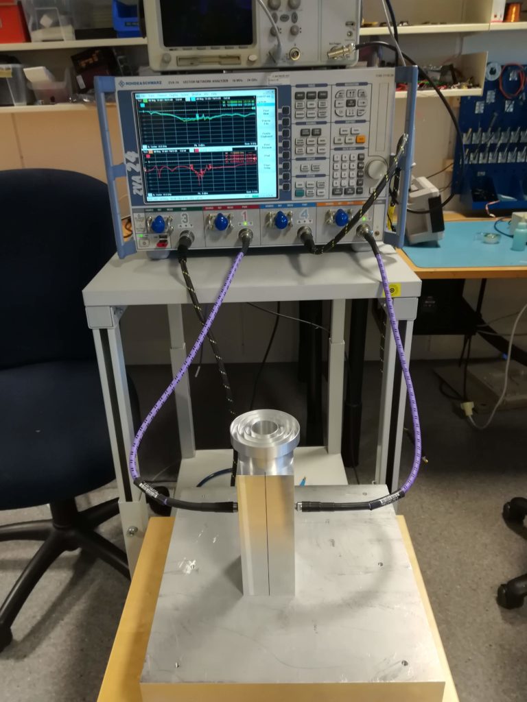
VNA measurement setup. 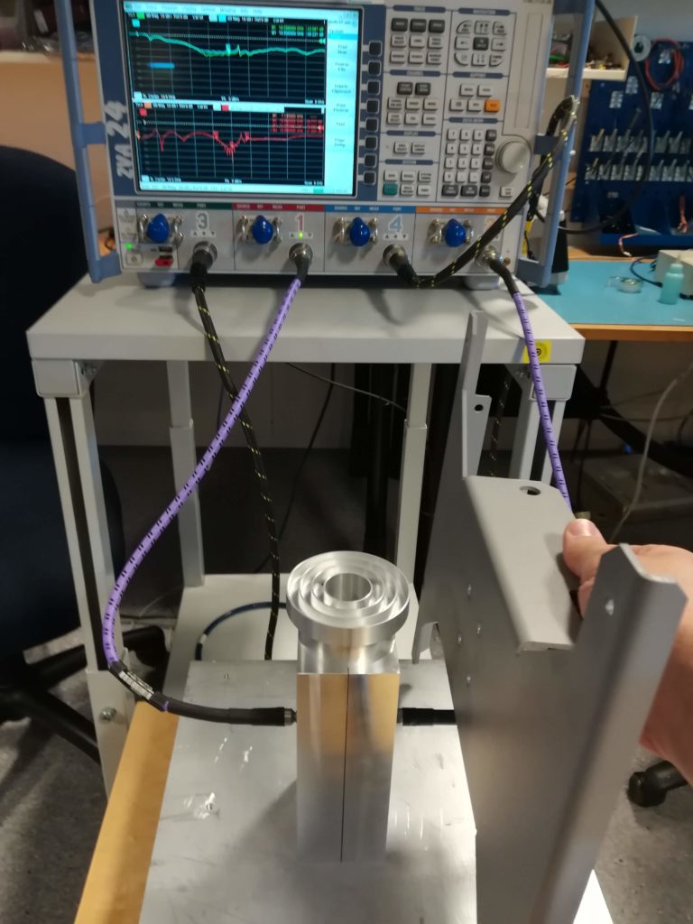
Return loss and isolation seems unaffected by close proximity to metal.
Finally, the match and isolation across both ports were measured on a ZVA24 network analyzer. One of the properties of the Chaparral style radiation part is the integral waveguide traps, these help supress sidelobes. It also gives the added benefit of immunity to changes near the antenna, as illustrated with the metal plate in the photo above.
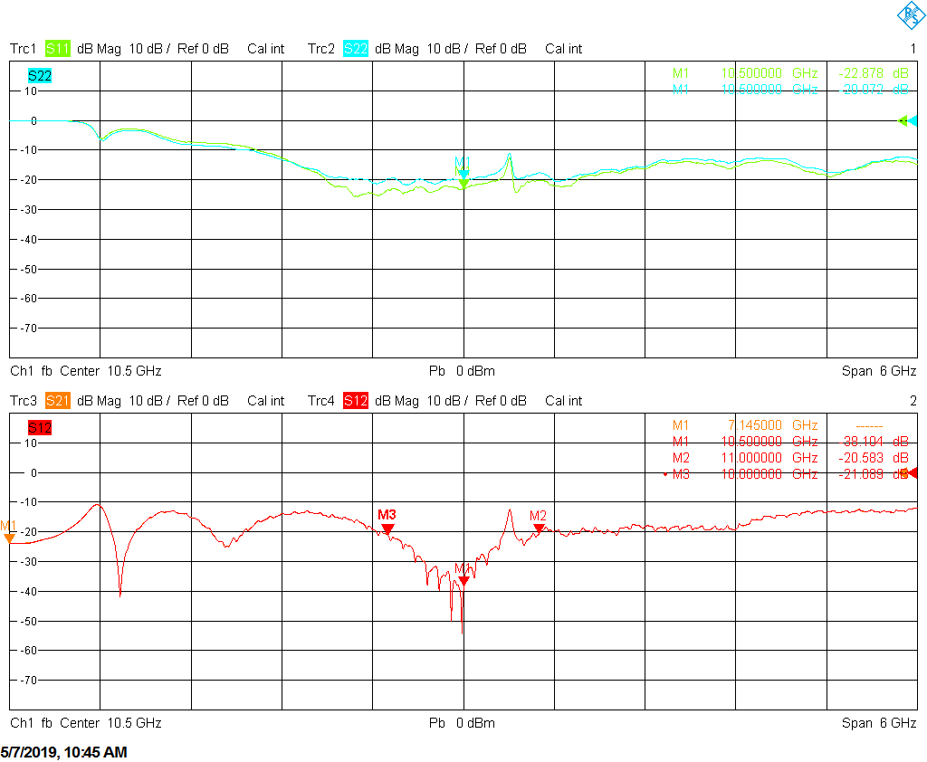
Return loss, isolation and patterns are all very impressive. Overall PE1RKI delivers a solid product, which will surely serve us well in the future. Now we need to take a step back, and figure out how to go about integrating the 3 cm EME station.


Leave a Reply