In January we wrote about our plans to deploy the 6 m (50 MHz) beacon LA2SIX. This week we are back to talk a bit more about the inner workings of the beacon, and to announce that our application for frequency and callsign has been approved. 🙂
LA2SIX will be fully operational from summer 2019, with initial tests starting as soon as the mountaintop beacon location has thawed. It will operate on 50.488 MHz, with 25 W into an omnidirectional antenna (vertical dipole) using the CW sequence “LA2SIX JP53EG BEEEP”.
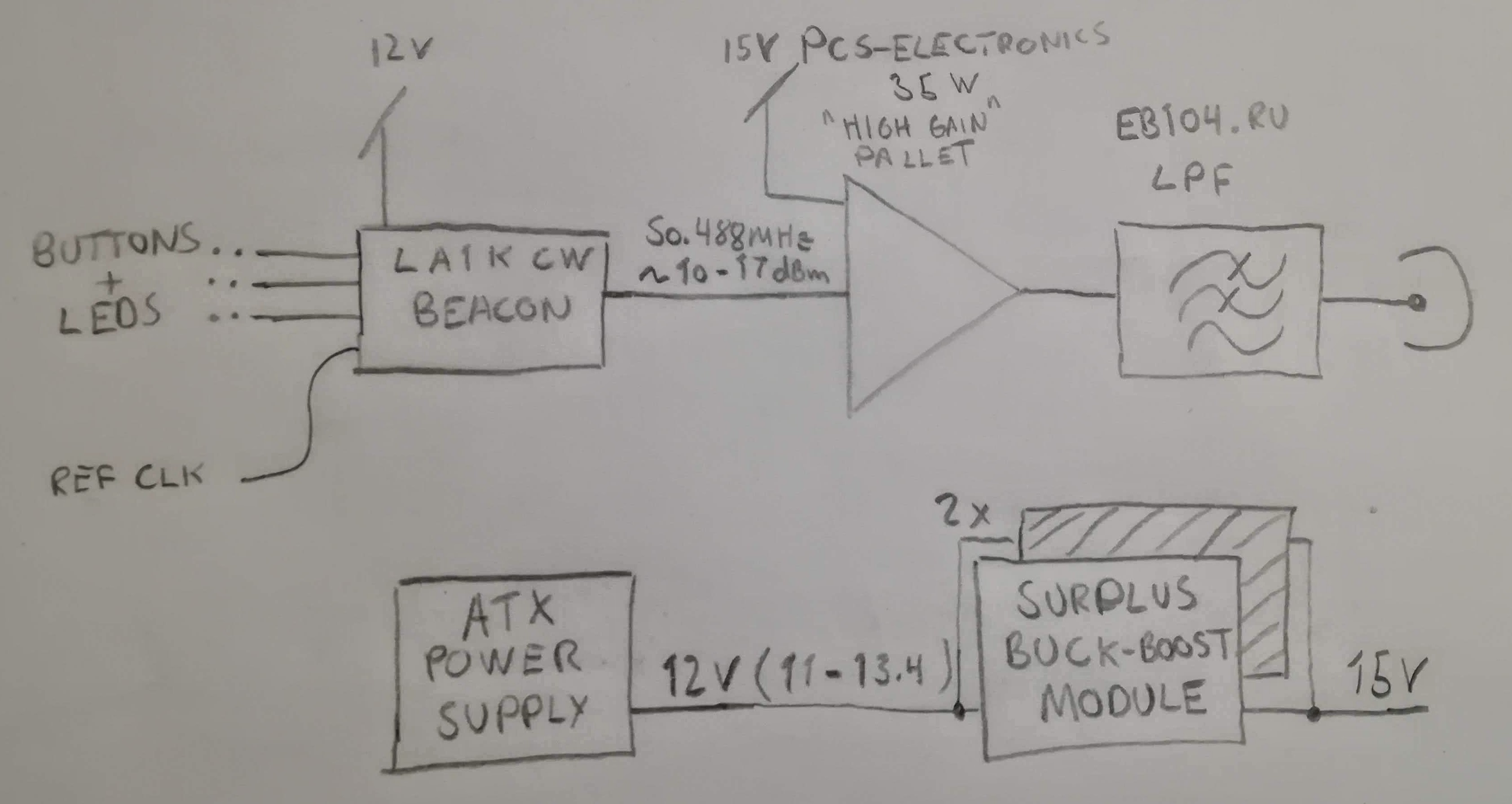
The meat of this post is the construction details for the beacon. We started off with a paper sketch, which in this case turned out to be a very close estimate for the end product (not that surprising, considering we lost the original sketch and re-made it based on the final product).
We have had a lot of success with the LA1K CW beacon platform. When preparing for LA2SHF (our 23 cm beacon, which is currently not operative due to an interference issue) we made an additional beacon card, so we were ready for another rapid beacon build.
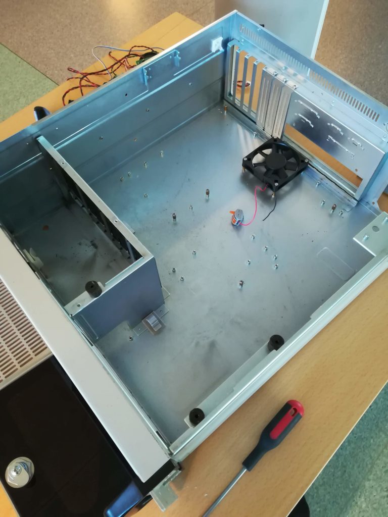
Gutted rackmount PCs make for excellent beacon houses. 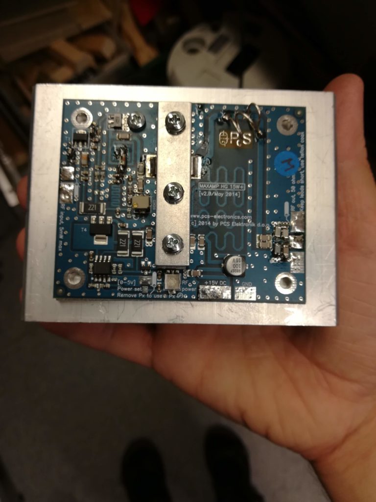
PCS-Electronics 35 W High gain pallet, with custom tuning. 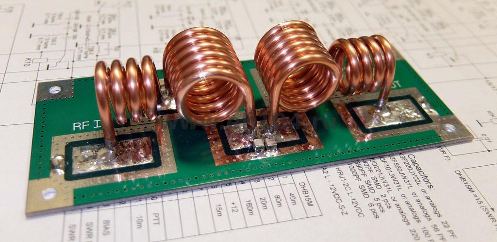
EB104.ru 50 MHz lowpass filter. Credit: EB104.ru
Other time-savers were the off-the-shelf filter and amplifier modules. EB104.ru have a lot of cool and affordable stuff. For this project we chose a low-pass-filter they sell (27$) for the 6 m band. Its 2 kW rating is definitely overkill, but hey – it was cheap.
The amplifier was a bit harder to find, as a lot of gain is needed to be able to go to 25 W from the 10-70 mW the CW beacon delivers. We reached out to PCS-Electronics, a store that sells various FM and TV transmitter equipment. They have a “High gain” pallet, which can be ordered for specific frequency ranges if you get in touch with them. This turned out to be a very economical solution, and we ended up paying 99,- EUR for a custom tuned amplifier. They also shipped the device very quickly, and we can absolutely recommend them for other projects.
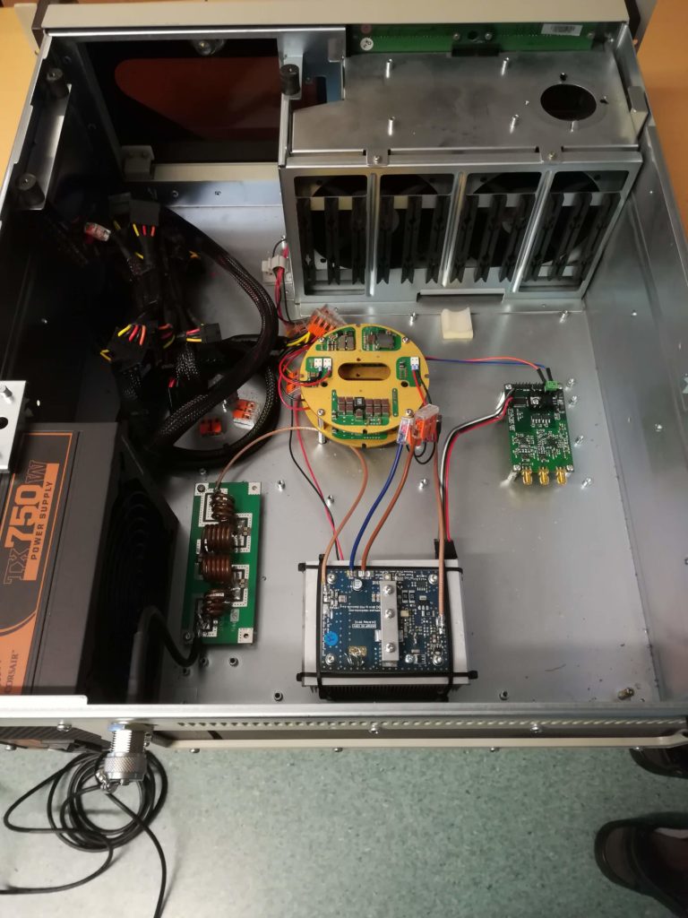
Initial placement of beacon parts. 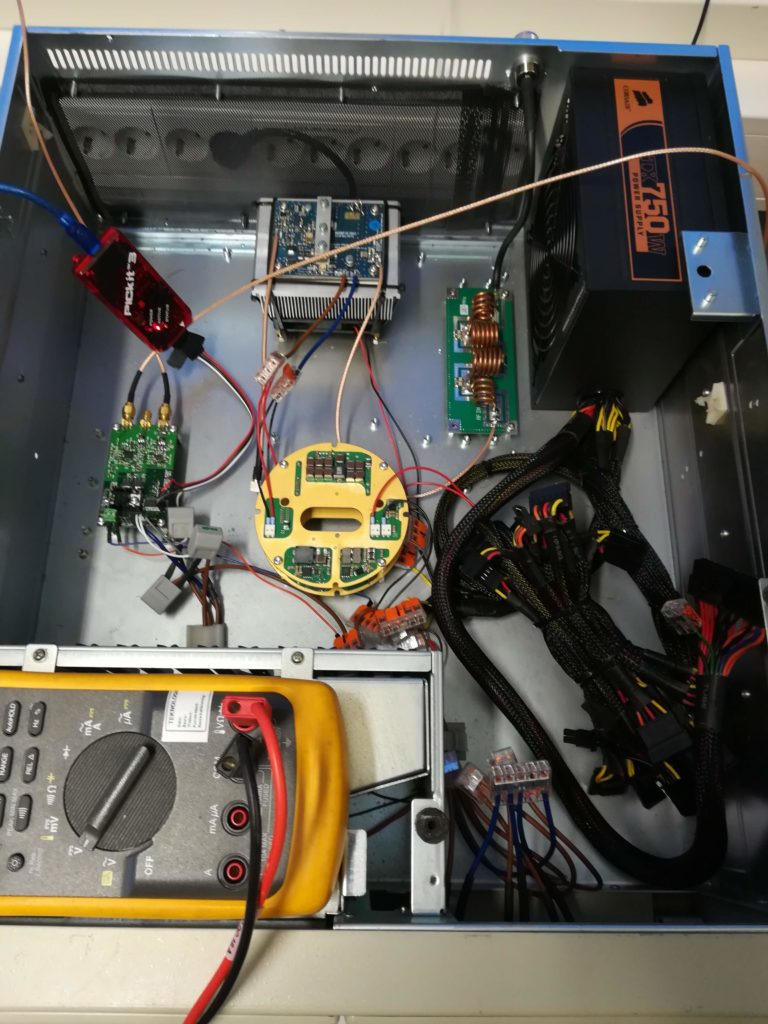
Wiring finish, programming and measuring. 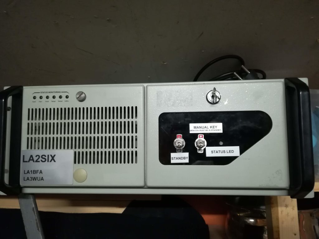
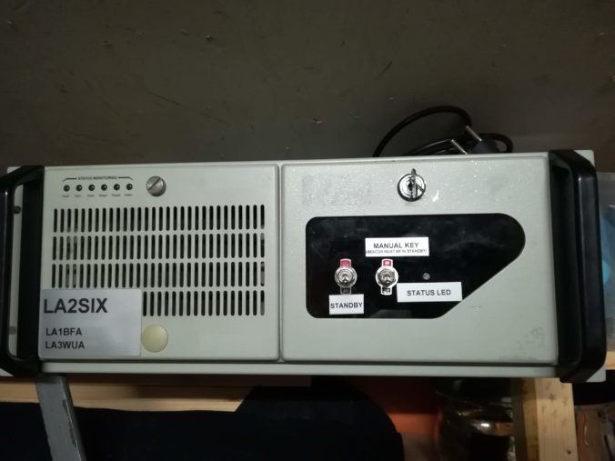
LA2SIX front panel.
After finishing the cabling work, we made some quick voltage checks before starting to trim up the output power. The amplifier made it easy to reach our 25 W target, no real problems were encountered – that is a first!
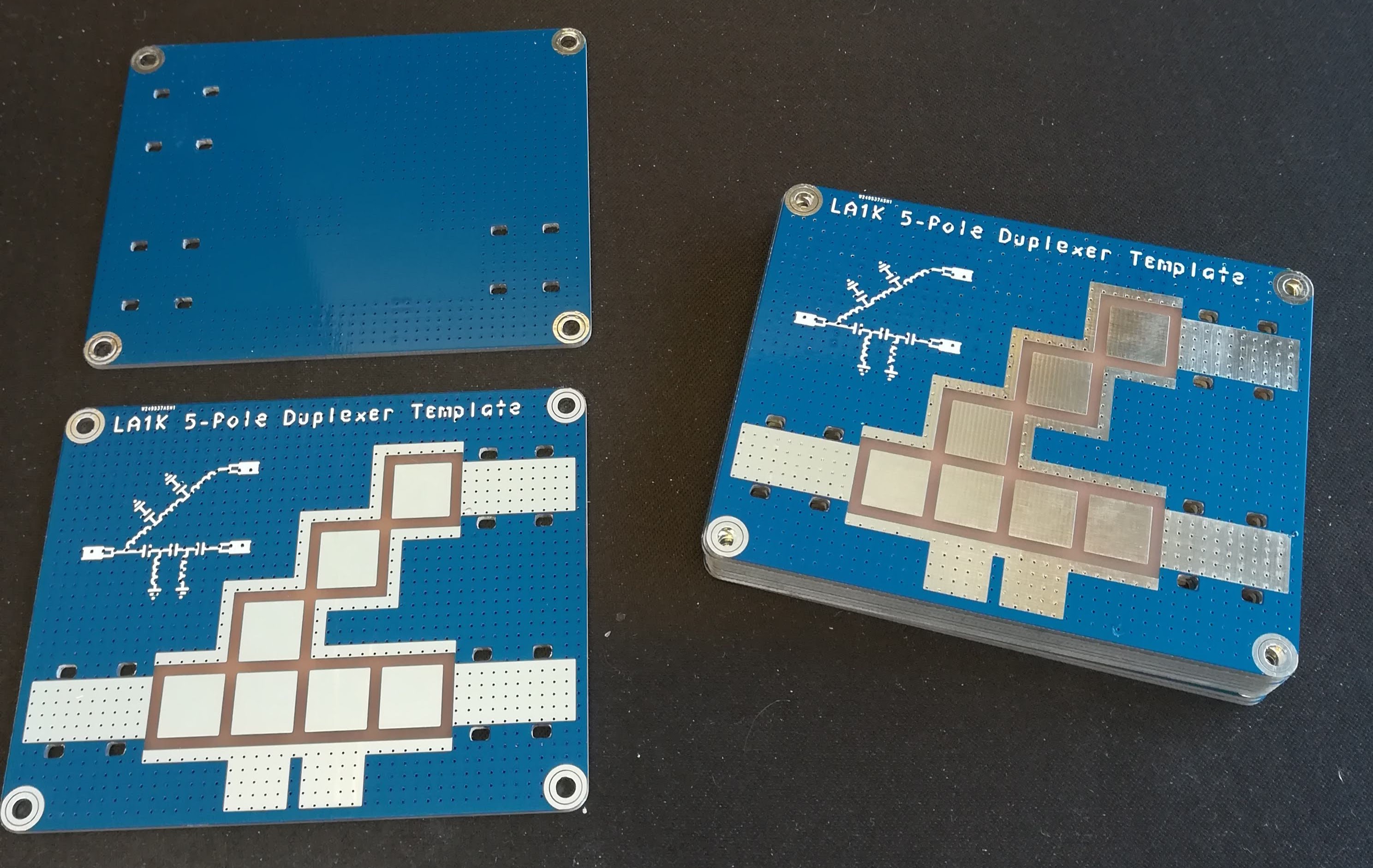
Future blog post spoiler: LA1K 5-pole diplexer template, which will be available open source.
As a small spoiler for a future post, we also received the boards for the diplexer (ignore the silkscreen typo!). This will allow us to combine the two beacons to be able to work on the same antenna, as we mentioned in the previous post on LA2SIX.
We look forward to getting the beacon installed, and are eager to receive the first signal reports.

Very cool! Where do you get the +15V supply from? Is there a step-up SMPS somewhere?
Also, what substrate was used for the diplexer PCB?
+15 V is supplied via the buck-boost boards seen in the middle of the beacon (a stack of two circular boards). The amplifier would probably work fine from 13.4 V from the ATX supply, but we wanted to squeeze a bit of extra power out of the device. Actually we’re running the amplifier with a good amount of back-off, so this might seem a bit weird – but the main goal is to increase device lifetime. Also, the buck-boost modules help clean up the signal a little.
As for the diplexer PCB, it’s made from generic FR4 (PCBWay two layer process).
Received the beacon twice here is southern England over the past week (mid-July 2019) via Es.
Whilst at all times it is relatively weak (about s3 max) I am so glad to hear the signal.
You have given me an idea on what I do with my old PC cases 🙂
Tusen takk for arbeidet ditt
Thanks for your report, Nick! We’re glad to hear that you are enjoying the beacon 🙂
73 de LA3WUA/Øyvind
Can you confirm the antenna currently in use?
In your article you state “omnidirectional antenna (vertical dipole) ” whereas I received information from another source suggesting it is crossed-dipoles (horizontal).
The antenna is currently a vertical dipole.