Recent additions of LA2VHF/4m (2015) and LA2SHF (2018) to our beacon park at Vassfjellet has increased the number of beacons ARK maintains to a total of 4 – from 2 and then 3 to “many”. Unfortunately, information about these beacons is scattered around the blog at la1k.no, and finding information about the frequency or transmitted signal is a challenging search activity (though luckily mostly contained within the beacon tag). But challenging no more! We’ve constructed a new page at https://www.la1k.no/beacons which lists the information in an orderly manner along with the expected transmitted signal and some history, which we hope will make life easier both for ourselves and others.
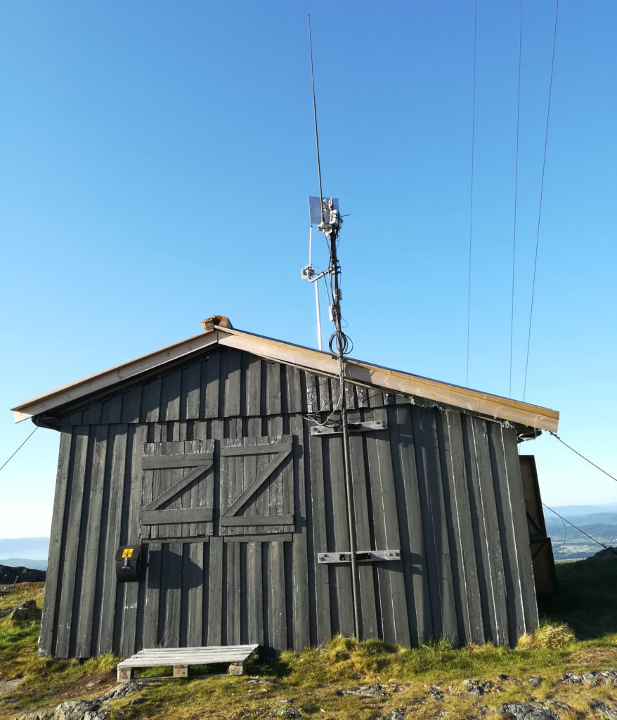
Beacon containment cabin at Vassfjellet. Photo: LA3WUA.
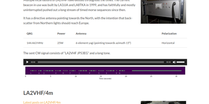
All our beacons transmit a morse signal at a regular interval. The beacons have been useful for the study of propagation conditions at the covered bands, and for debugging and measurements of our antennas. We plan for the future to extend to a 6m beacon if we can obtain a license for it, as well as possibly covering the entire 1-10 GHz range. We’re also making plans for extending the transmitted signal from a simple morse signal to other digital modes like PI4, to enable easier decoding under weak propagation conditions.
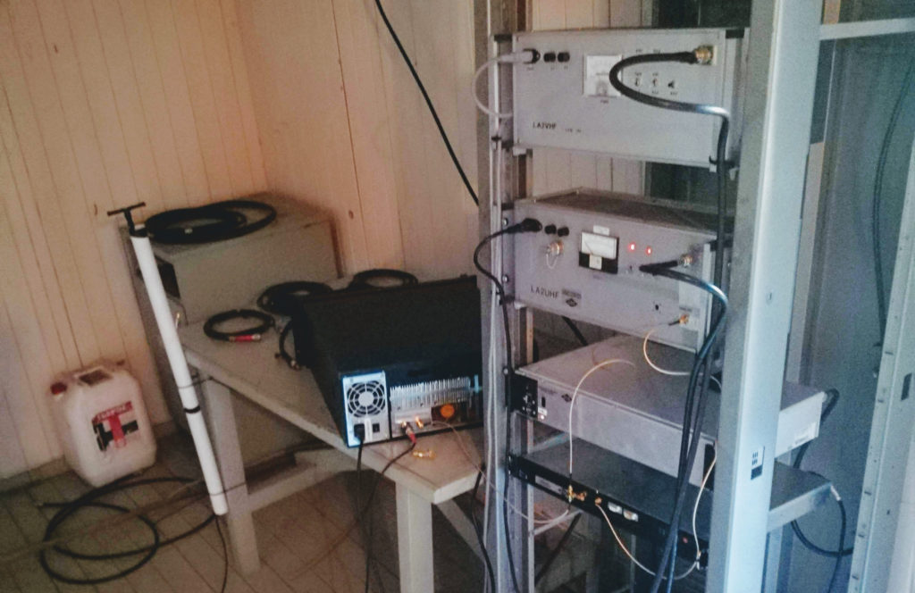
Beacon rack: LA2VHF, LA2UHF and LA2VHF/4m from top to the center of the rack. LA2SHF has been left outside in the cold/on the table. LA2SHF’s sleeve dipole antenna can be seen in the white tube to the left. Photo: LA3WUA.
Like already mentioned on the page: If you hear any of these beacons, let us know! We appreciate reports on DX clusters, or direct contact through email. DX cluster reports or emails from operators who have heard our beacons are invaluable in investigating propagation phenomena.
Data acquisition
The page contains waterfall diagrams and audio samples. The data acquisition process is outlined below.
LA2SHF was measured using the parabolic dish, while LA2VHF/4m, LA2UHF and LA2VHF were measured using the 2m/70cm-array. All beacons were measured using an USRP B210 at sample rate f_s = 100 MHz through a GNU Radio-companion-based Python script, with the center frequency f_c being placed so that the beacon frequency was centered between f_c and f_c + f_s/2. IQ samples were output to file, and later post-processed using the Fast Fourier transform to obtain the shown waterfall diagrams.
The audio samples were generated by running the raw data through a band pass filter of width 880 Hz (asymmetric with complex taps), centered on the beacon frequency, and then shifting the start frequency of the filtered block down to DC level by multiplying with a complex cosine with the appropriate, negative frequency, which forces the beacon frequency down to 440 Hz.
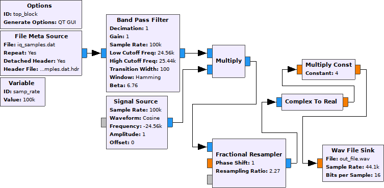
GNU Radio flowgraph for generating audio. The generated Python script top_block.py was modified to set band pass filter ranges and frequency shift automatically from metadata and beacon frequency (extracted from the filename), and for setting output and input filenames more conveniently.
The signal was finally resampled from 100 MHz to 44100 Hz, and the real part was taken of it and saved to an audio file. This effectively makes the beacon signal appear to have a tone close to 440 Hz (a comfortable A tone) in the audio files.


Leave a Reply