3D-printing is a very cool way to make stuff, and we have wanted to test it for amateur radio projects for a long time. Jordi – LB0OH needed an antenna for an Outernet Dreamcatcher, which made for a perfect excuse to test this manufacturing method.
Searching around on the web, it appears that there are quite a lot of designs to chose from for 3D printed antennas for L-band. We ended up with a design by Tysonpower on thingiverse. From this collection we printed the 4 turn helix with Right Hand Circular Polarization (RHCP).
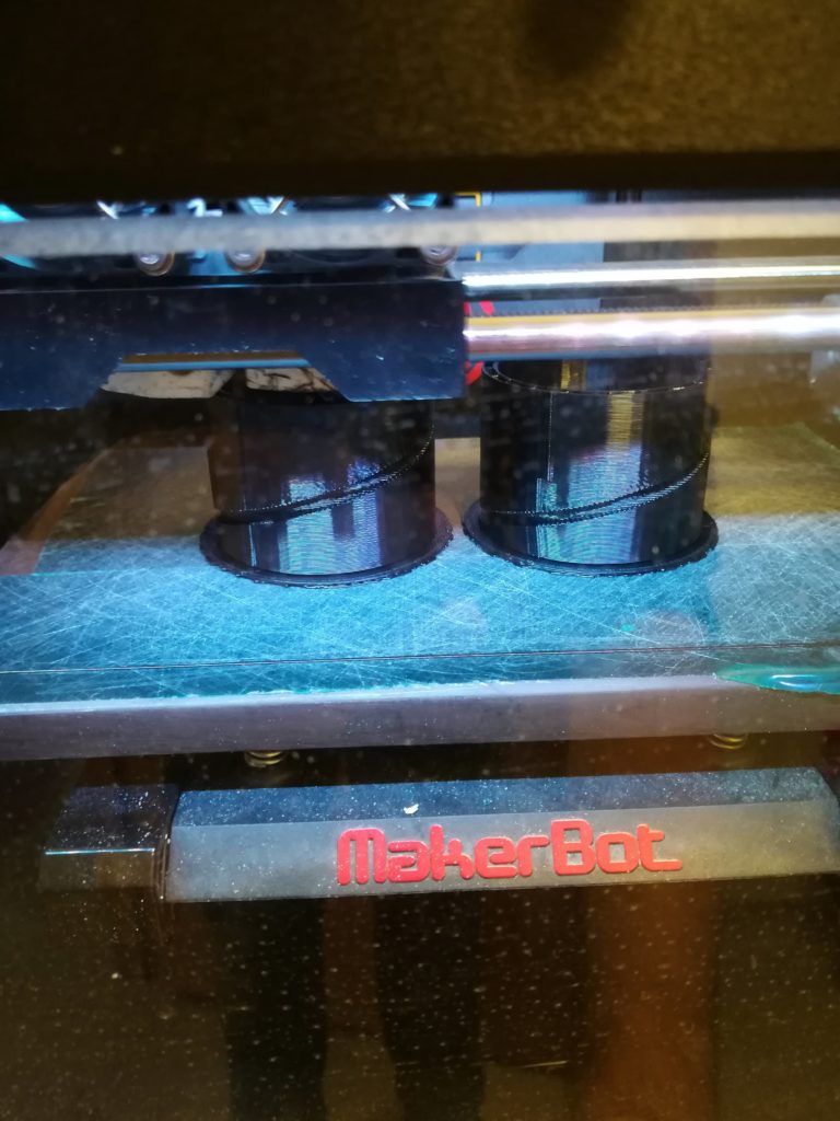
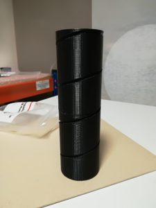
Half way through the 3D printing cycle.
To fit the design into the MakerBot Replicator 2x we had available, we cut the helix in half. This allows for printing it in a standing orientation, and makes warping less likely to occur.
-
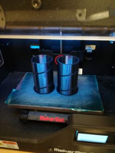
- Printing finished.

-

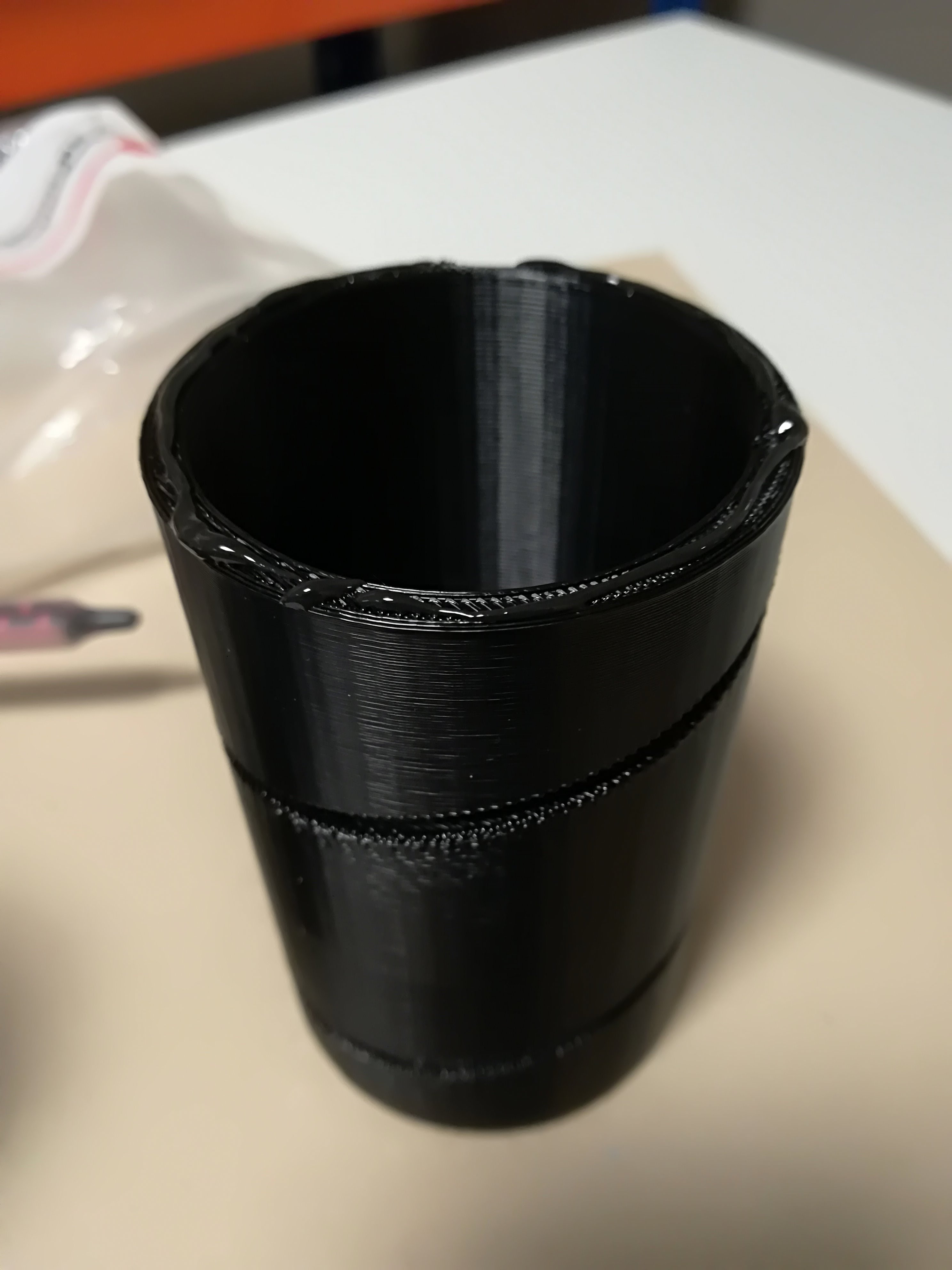
- Closeup of one of the helix halves.
-
- Two helix halves glued together.

Once the 3D print is finished, there are a couple of more steps and materials needed.
- Some wire
- Metal backing – anywhere from 20 cm x cm to 30 cm x 30 cm
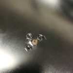
- A M3 nut and bolt
- A SMA connector and suitable nuts and bolts
- Strong glue
We prepared the metal backing by drilling a hole in the center of the square metal piece, then another hole was made around 3 cm away from the center hole. This is where the SMA connector is attached. Next the holes for the SMA connector were drilled, and the connector fastened.
-
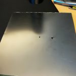
- Center hole and SMA hole drilled.
-
- SMA connector fastened to the metal backing.
-
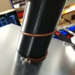
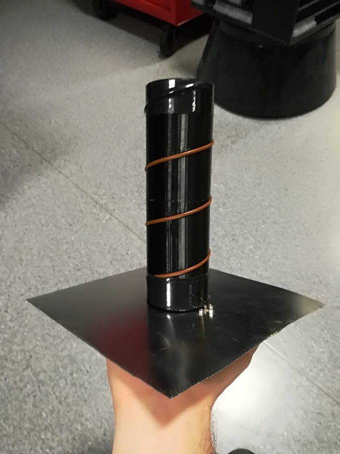
- Brown electrical wire added and soldered to the centre of the SMA connector.
The performance of the antenna was checked on a network analyzer. Initially we were having trouble getting it to match properly. After some fiddling we realized that the distance between the quarter wave matching line and the metal backing was too large. By bending the wire out of the track in the print and pushing it down closer to the metal we were able to get the performance we expected.
The axial mode helix has an impedance somewhere between 100 and 200 ohm, meaning that a matching structure must be used to bring it to 50 ohms. The matching scheme that is employed in this design is known as a quarter wave impedance transformer. By adjusting the distance to the ground plane, the impedance of the matching section is changed. This means that there is an optimum distance, which makes the antenna impedance matched to the system impedance.
-
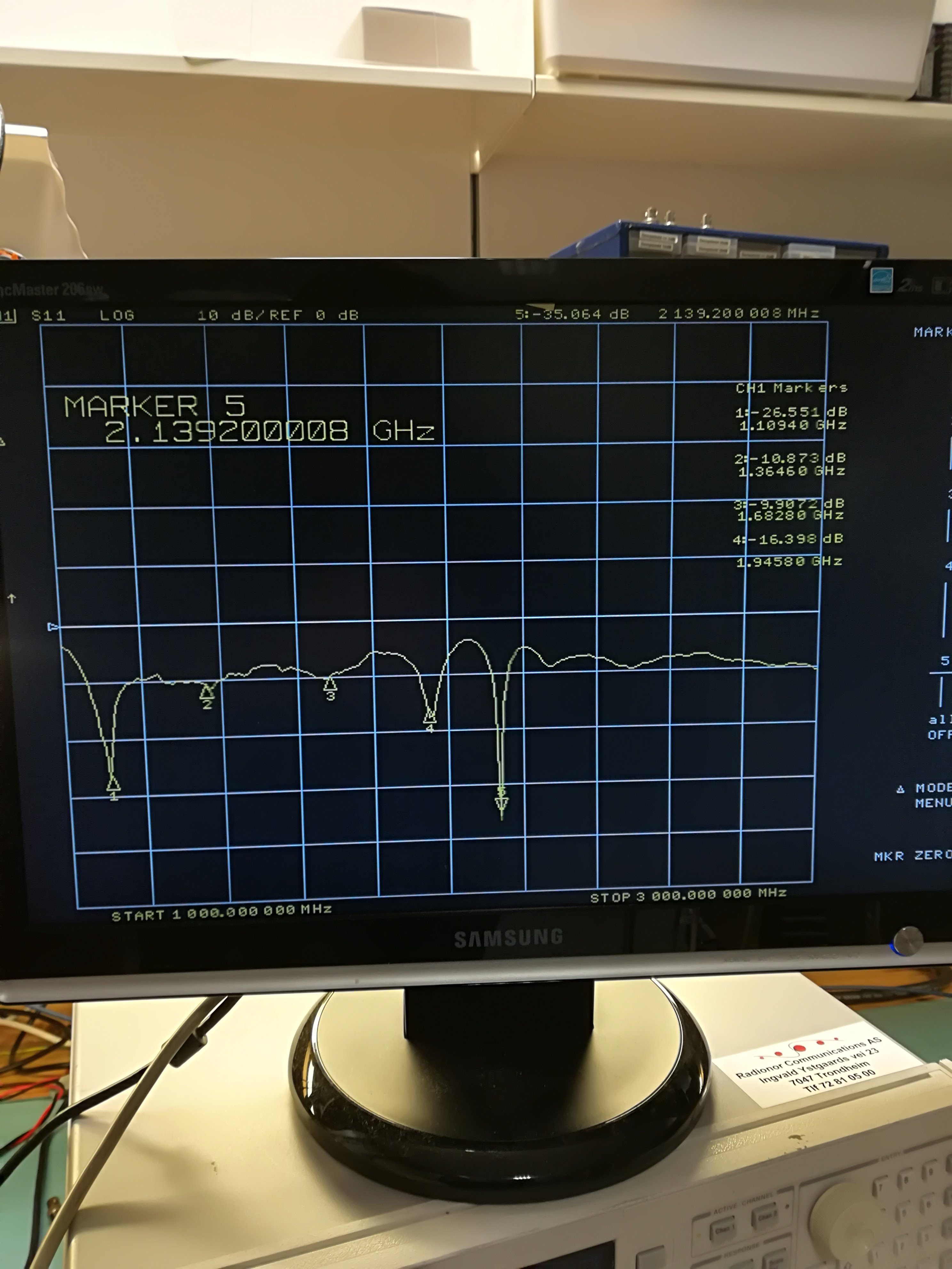
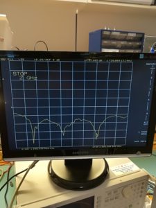
- S11 for the antenna before finding the proper distance to the ground plane. Note: the expected center frequency is 1550 MHz.
-
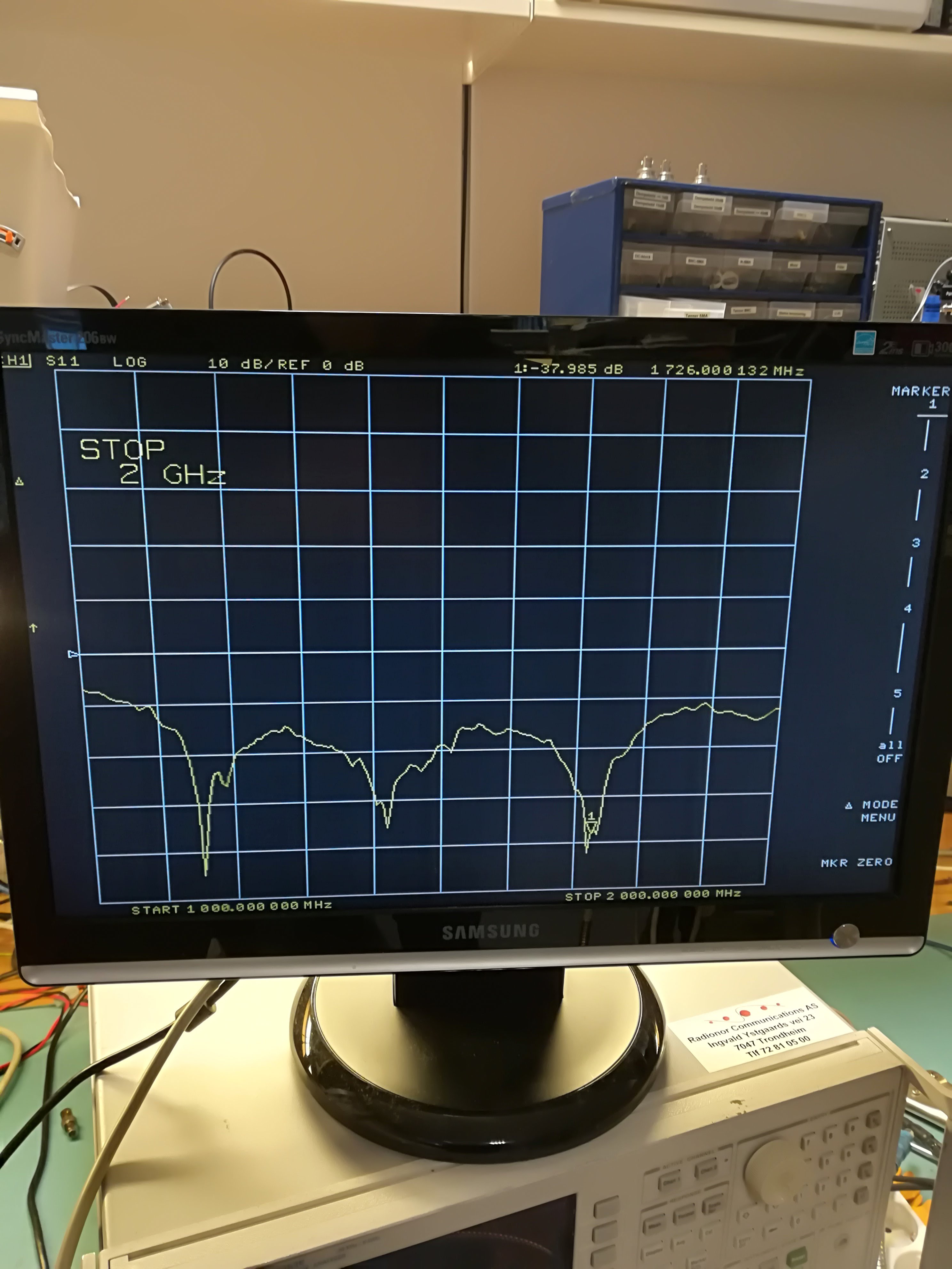
- S11 for the antenna after the matching distance was optimized.
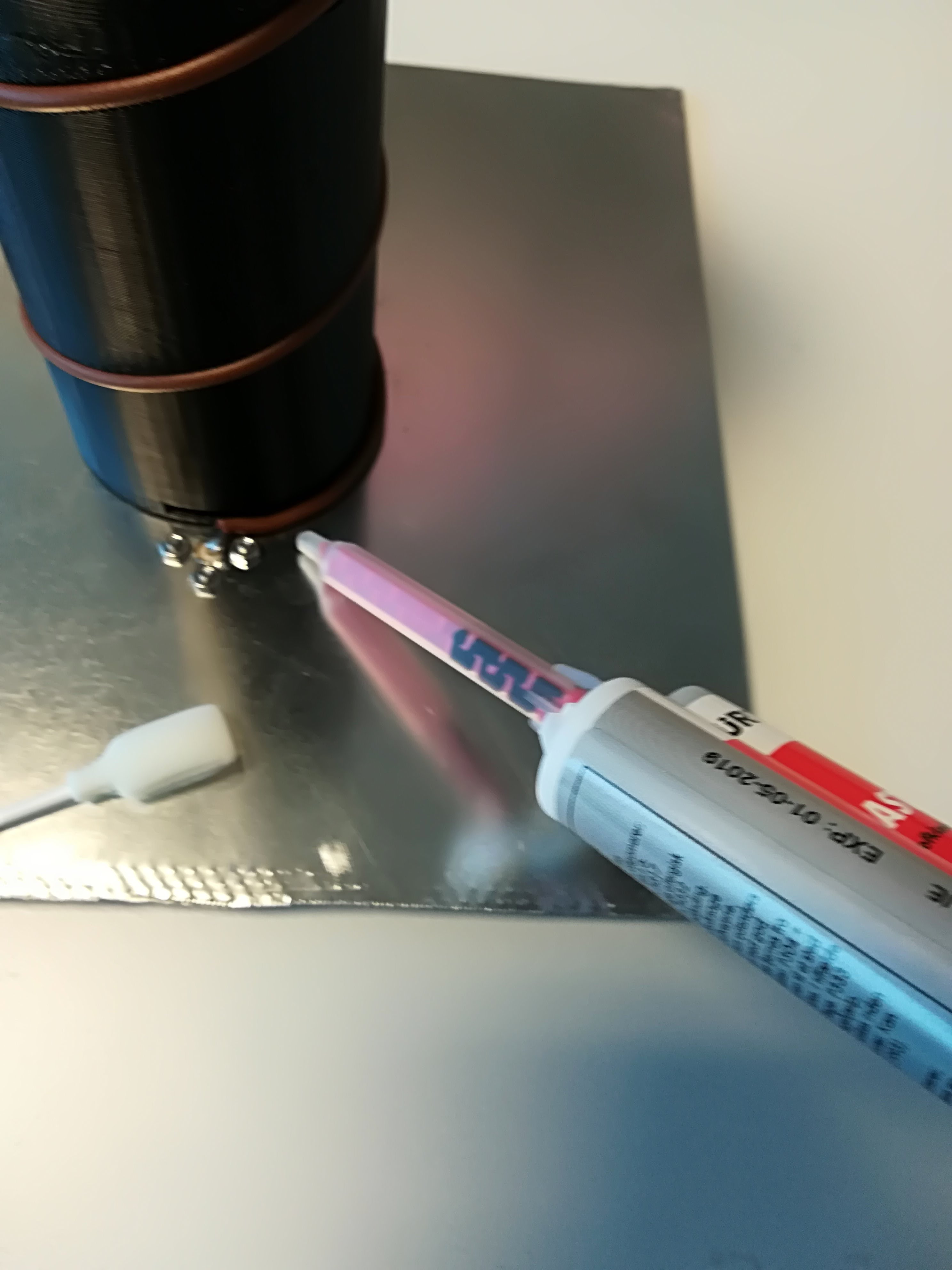
In order to keep the antenna in place, a two-component glue is used to affix the sections together.
-
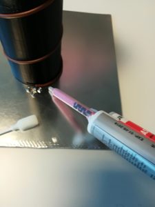
- Adding glue to the quarter-wave matching section.
-
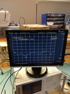
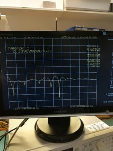
- S11 after the glue is applied.
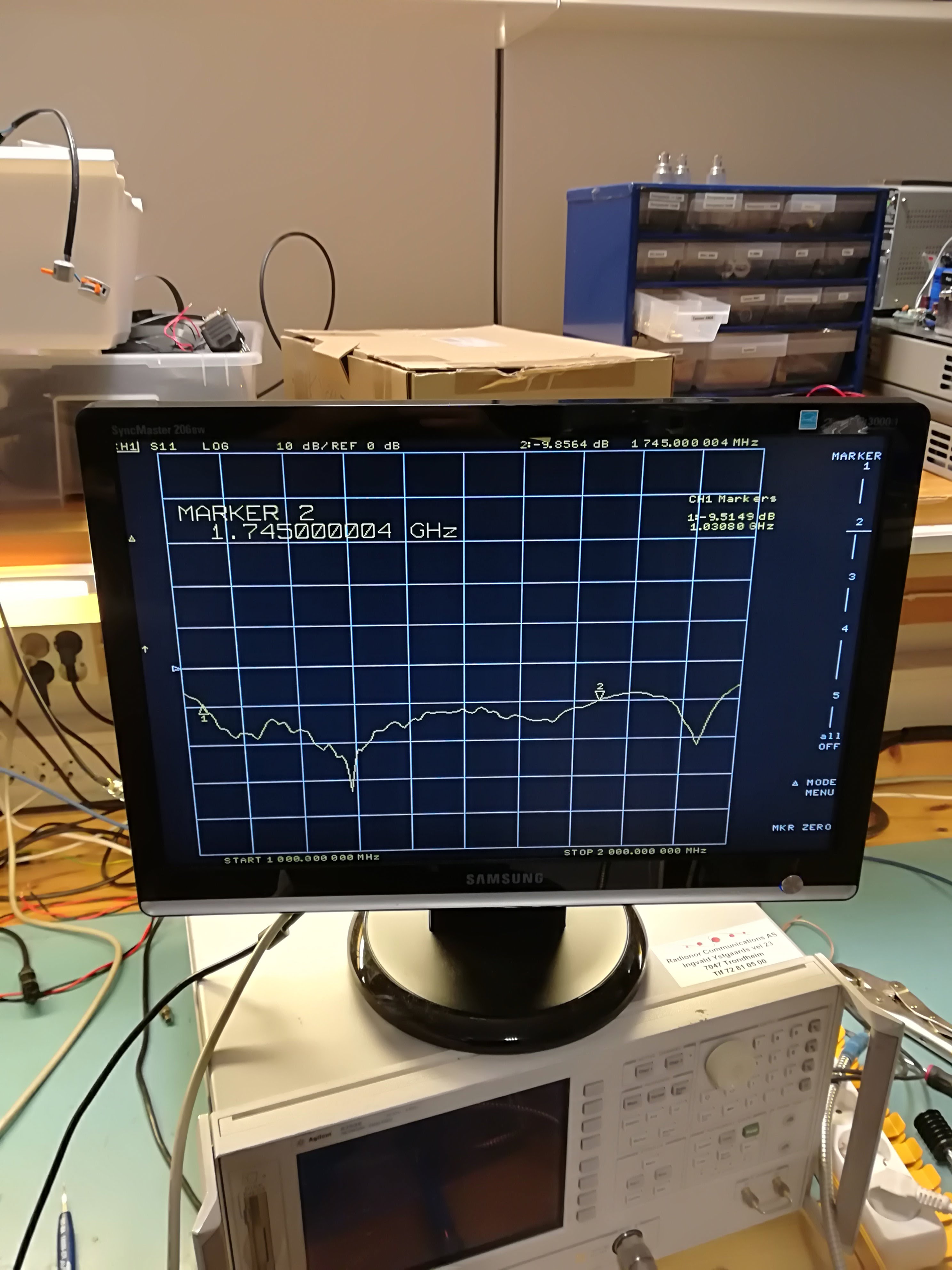
From the final measurement it seems that the glue either moved the quarter wave section, or that the glue has a dielectric ability that affects the matching structure. Nevertheless the match is -10 dB (2.0 SWR) over 1.1 GHz to 1.7 GHz, with a decent dip of -20 dB (1.1 SWR) at around 1.3 GHz (23 cm amateur radio band).
It should be exciting to see if the antenna is adequate enough to receive Outernet packages, in which case we might update with another post.


Leave a Reply