
For a long time we have wanted to have a beacon for propagation studies and prototyping/debugging in the 23 cm band. Due to the recent activity on the 1 to 10 GHz project, the need for a beacon has resurged. After a period of intense work, we are excited to announce that we have gotten the LA2SHF beacon active in test operation!
LA2SHF operates on 1296.963 MHz with a A1A CW sequence consisting of “LA2SHF JP53EJ” followed by a 10 second carrier. The output power is 30 W onto a sleeve dipole. LA2SHF is currently situated at LA1BFAs house in JP53EJ, but we will move the beacon to our beacon-site at Vassfjellet once the snow thaws (expect this is May/June). The current QTH is quite low altitude, so we expect that it might be hard to hear the beacon during test operation. If you do hear the beacon we would love to hear a report on la2shf@la1k.no, or on your favorite DX cluster.
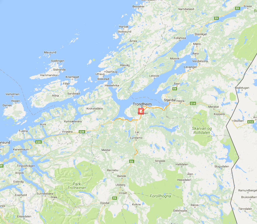
JP53EJ region (red square) on a map overlay of the southern part of Trøndelag.
ARK has held the LA2SHF license since 1979, and several attempts at getting the beacon running have been made since then. Most notable is a working beacon in the 1980s that had to be taken down due to interference to a air traffic control radar at Gråkallen.
The 1980s edition of LA2SHF.
The new beacon builds upon the LA1K CW beacon PCB and firmware created by LA3JPA (with help from LA1BFA and LA7VRA) in 2012. The project is available open source on github. In addition to the CW beacon, amplifiers are needed in order to bring the output power up from approximately 15 dBm to 45 dBm (30 W). Bert Modderman, PE1RKI, provided us with a great custom tuned driver/power amplifier pair that allows us to do just this. We also purchased an interdigital bandpass filter and a circulator from him.
Block diagram of the beacon.
The purpose of the bandpass filter is to reject harmonics and nearby transmitters. Previously we have had an issue with one of our beacons, where nearby transmitters would modulate the exciter, causing unintentional spurious behavior. The bandpass filter should make sure that this does not happen.
A circulator adds additional protection to the power amplifier. If the antenna is disconnected or damaged, the reflected power from the antenna will dissipate in the termination load of the circulator, ensuring that no harm is done to the power amplifier.
The build was started by assembling the CW beacon PCB. Parts were ordered from Digikey using the supplied Bill of Materials (BoM). PCBs were ordered from DirtyPCBs using the gerber files (PCB production files) supplied on Github.
-

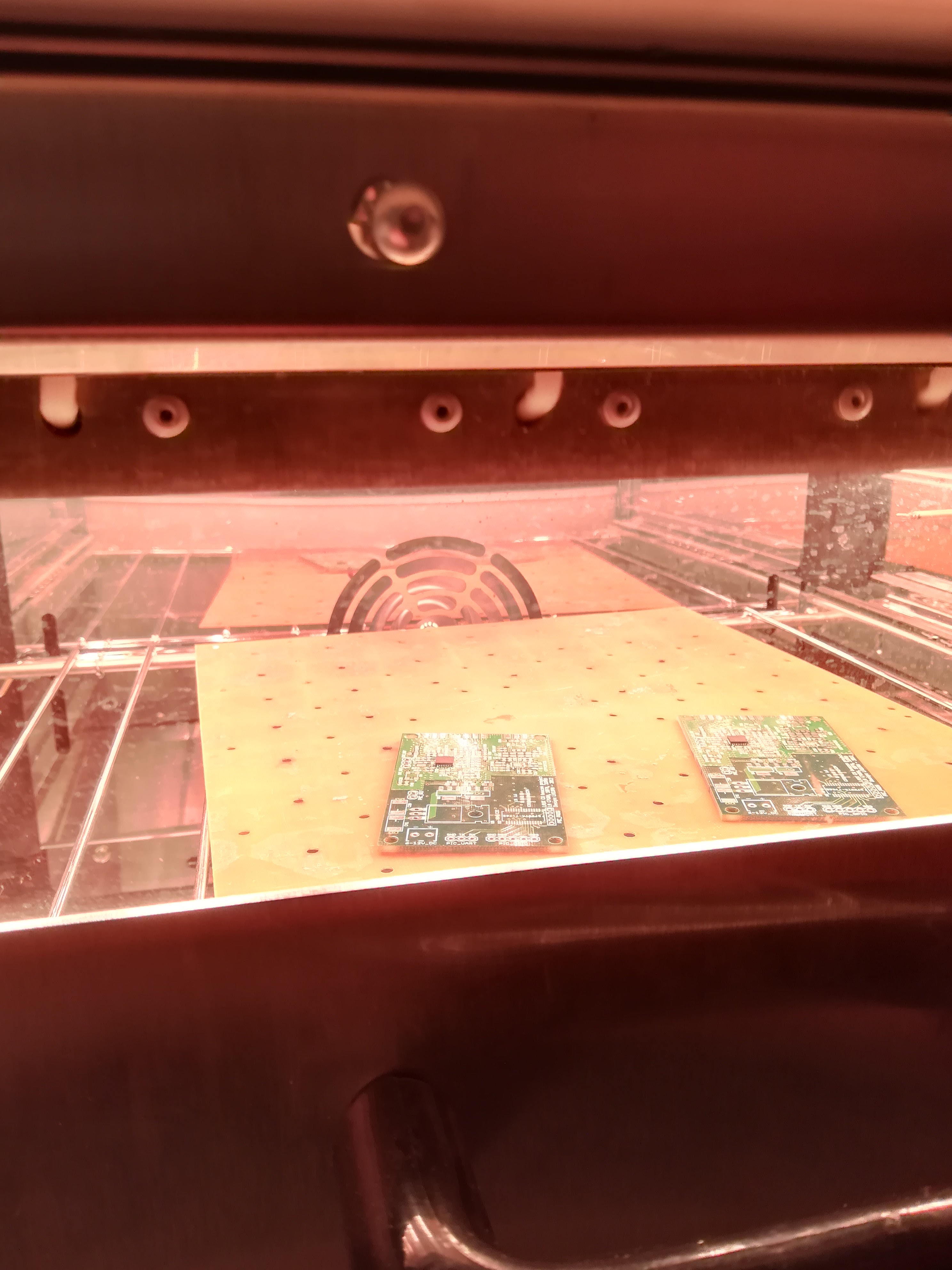
- A reflow owen and solder paste was used to solder the integrated circuits. Two beacon PCBs were produced, one for the beacon, and one for future projects.
-

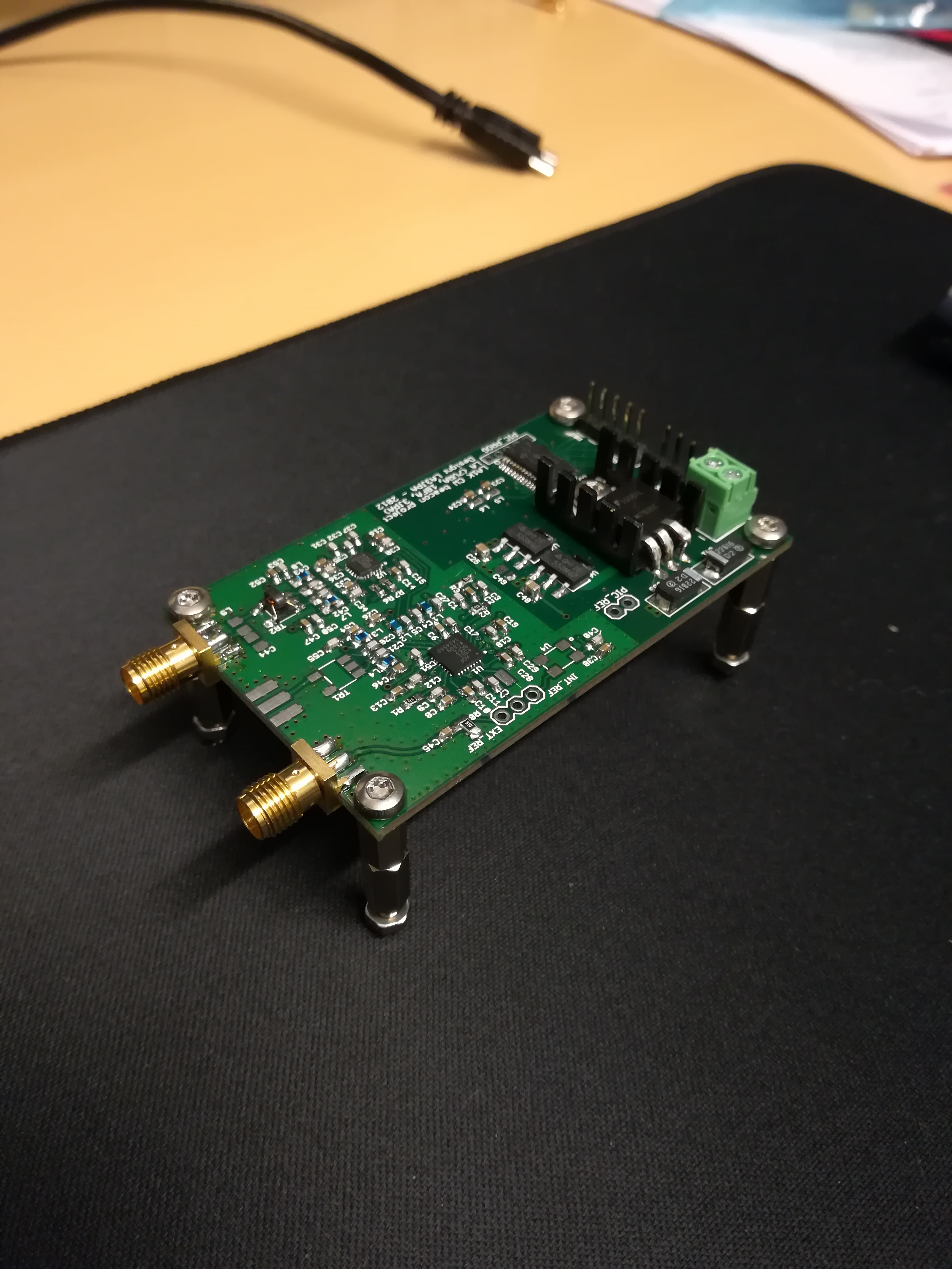
- LA1K CW Beacon PCB sits at the core of the LA2SHF beacon.
-

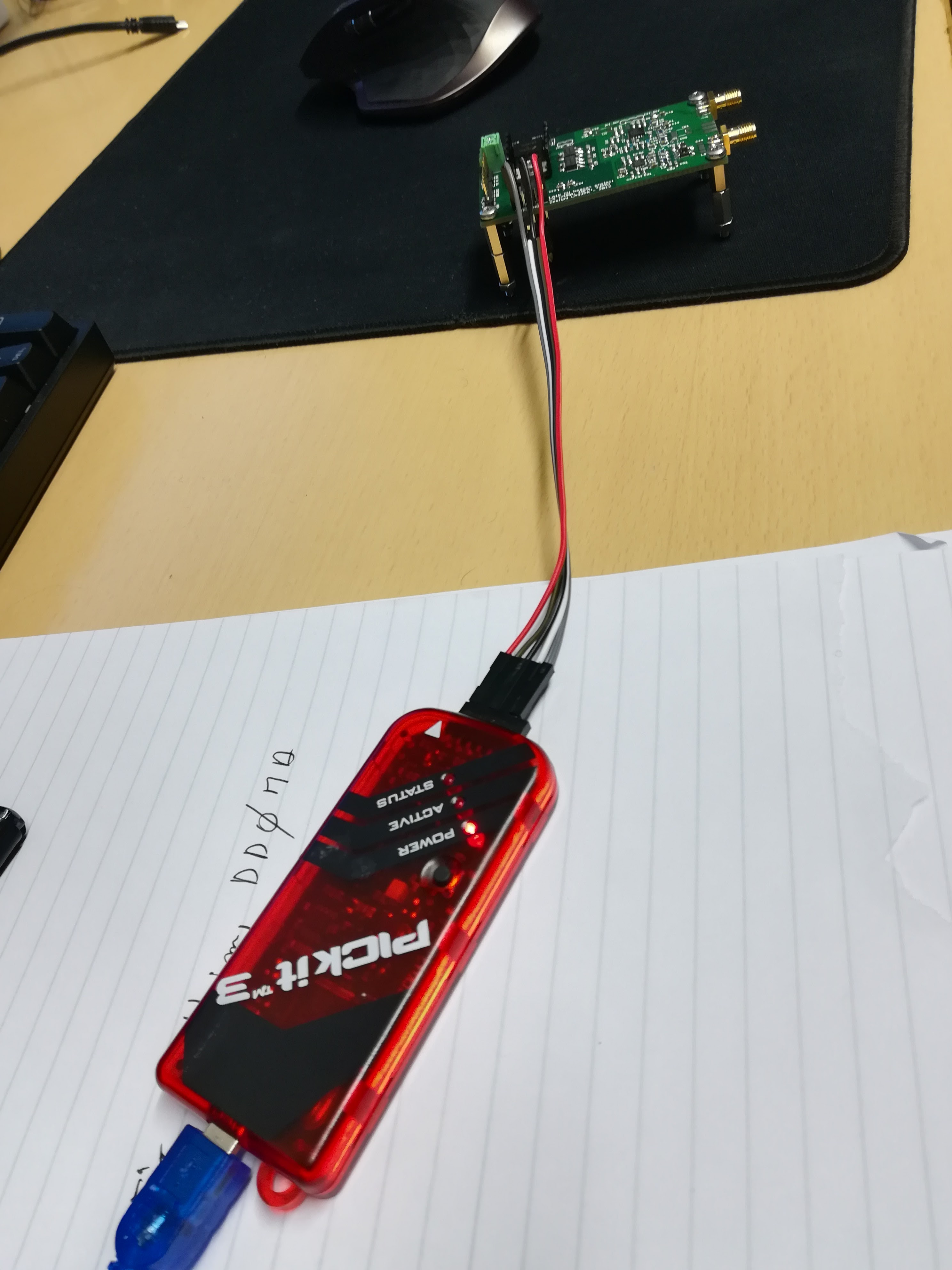
- Programming the first unit with a PICkit programmer.
-
- First attempt at powering up the PCB. No magic blue smoke!

-
- First output test. The beacon was programmed to transmit on 1296.5 MHz for this test.

-

- The waterfall view displays parts of the beacon sequence.

The PCBs are programmed using the MPLAB-X IDE for Linux (Windows and Mac versions also exist). In order to adapt to the previously developed code, some minor modifications are needed. Changing the frequency and CW sequence was done by altering line #56 and #57 in main.c. Additionally all references to plib.h were replaced with xc.h.
A thermal imaging camera allowed us to check the thermals of the CW beacon PCB. As expected the voltage regulators and RF ICs are the parts that get hot. All seems to be in order, but the temperature got all the way to 59 degrees after a couple of minutes. As a security measure, a fan is placed next to the PCB inside the final chassis.
-
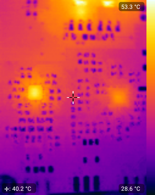
- VGA (left) and synthesizer (right) temperature profiles.
-
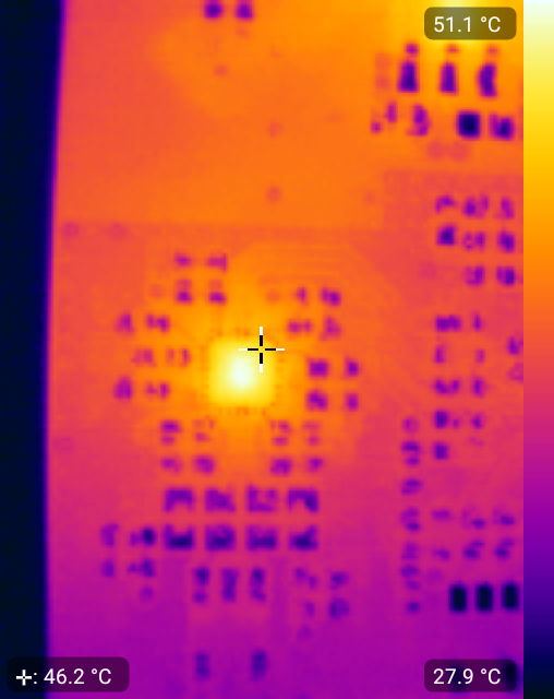
- Close-up of VGA circuit.
-
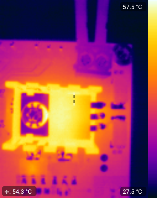
- The heatsink on the LM7805 voltage regulator is by far the hottest part of the board.
Once the parts from PE1RKI arrived, we were ready to start the build. After unboxing we eagerly connected the filter and circulator to our network analyzer to check that everything was in order.
-
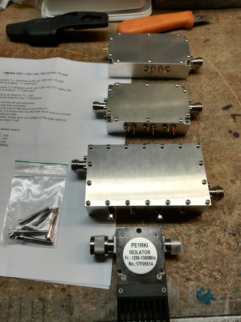
- PE1RKI: Driver, power amplifier, bandpass filter and circulator.

-
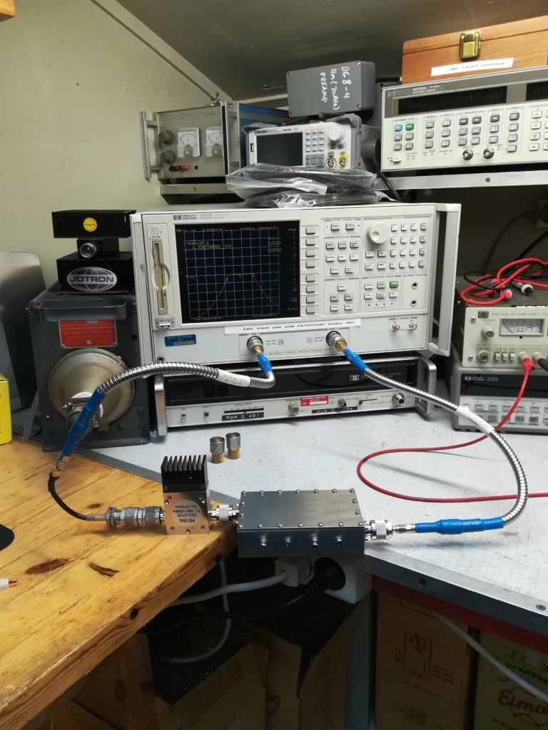
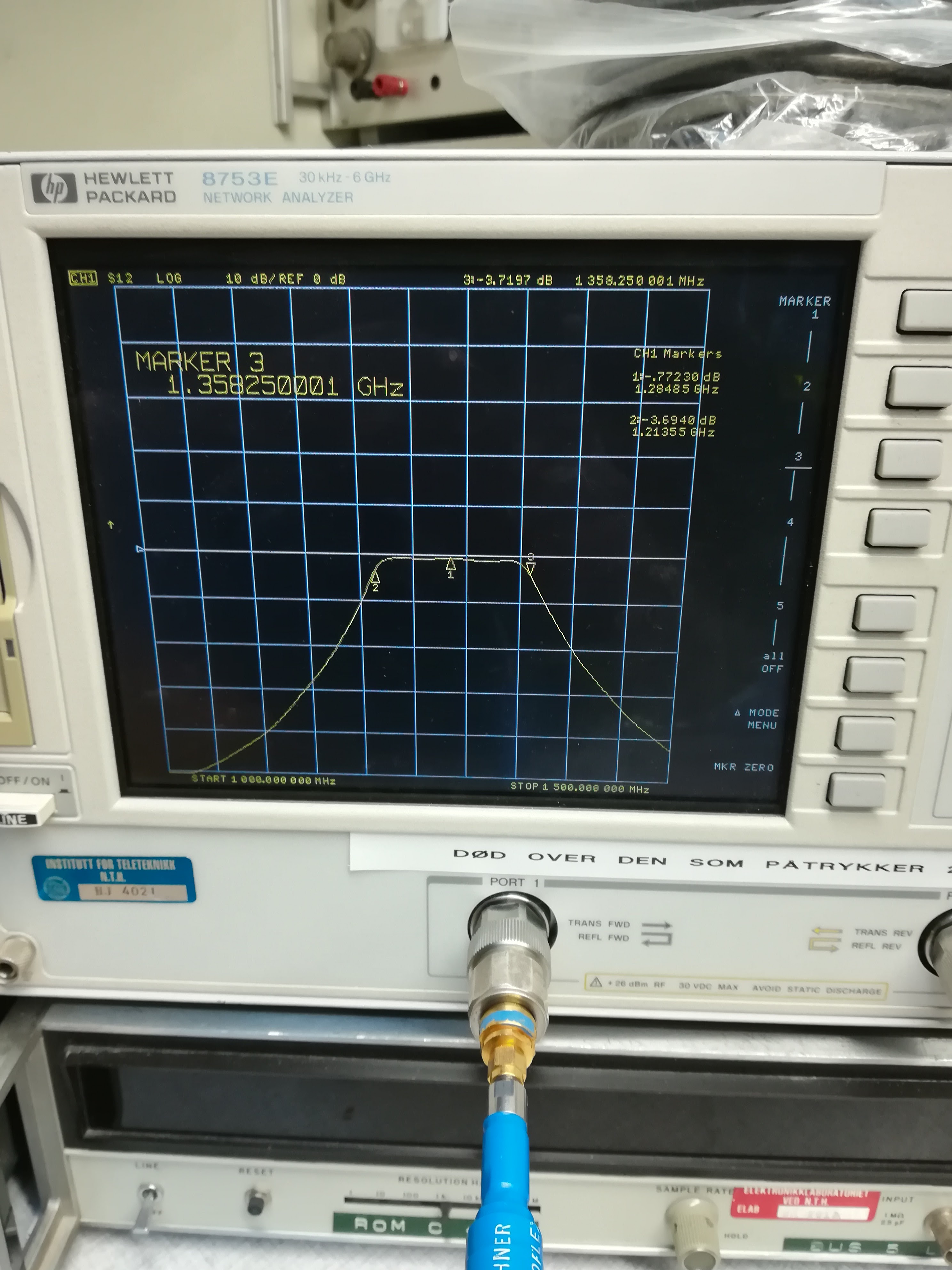
- As a sanity check, we measured the filter and circulator on our network analyzer.

-
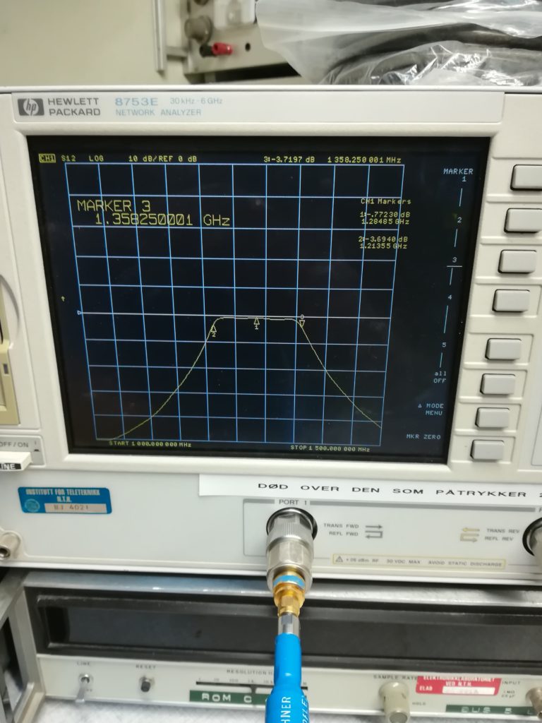
- The bandpass characteristic is clearly visible. The loss is about 0.5 to 1 dB at target frequency, which is acceptable.
The most time-consuming stage was integrating all the components inside a chassis. At Vassfjellet, the other beacons are mounted in a 19″ rack, so we needed something that would fit in there. Luckily we had a surplus computer cabinet that was up to the task. Most of the work here consisted of drilling and tapping holes, and hooking up wires to all the parts.
-
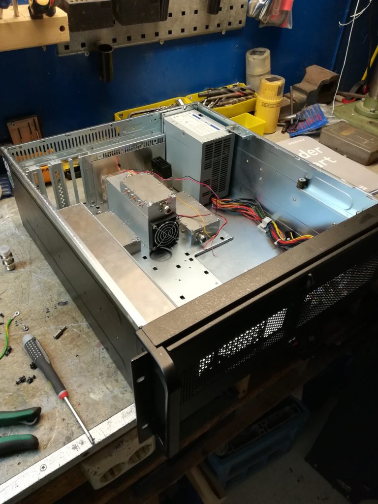
- Test fitting the amplifiers and power supplies inside the chassis.

-
- Driver attached to its cooling block. Thermal compound is applied under the amplifier for better heat transfer.

-
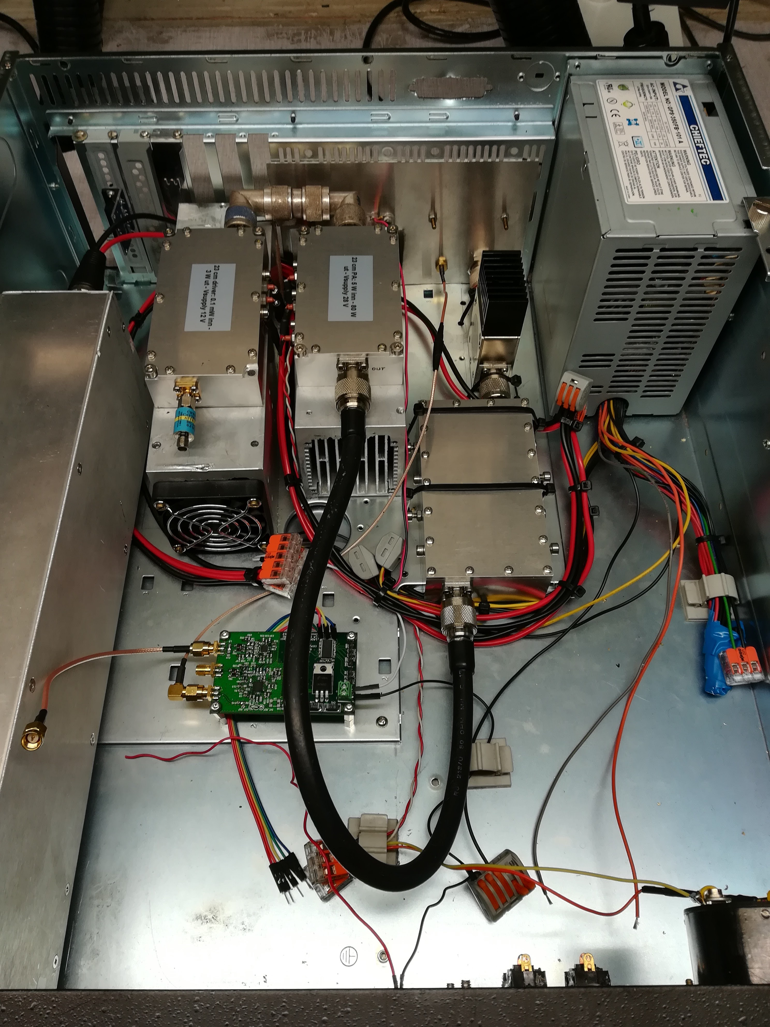
- Partial completion of the internal cabling.

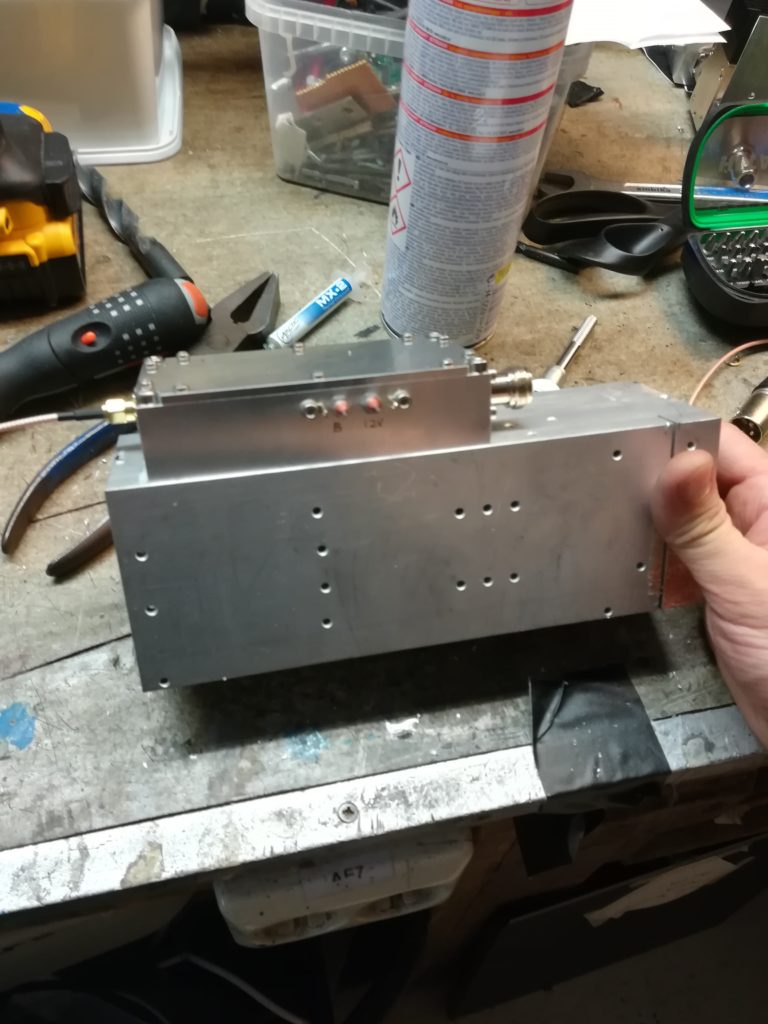
-
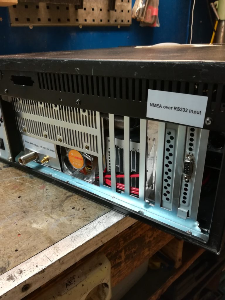
- In addition to RF output, there are inputs for 10 MHz reference and NMEA on the back panel.

-
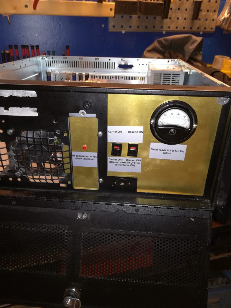
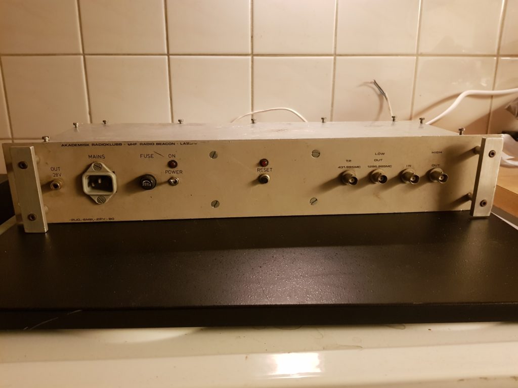
- The front panel has a level monitor, and two levers for debug operation.

-

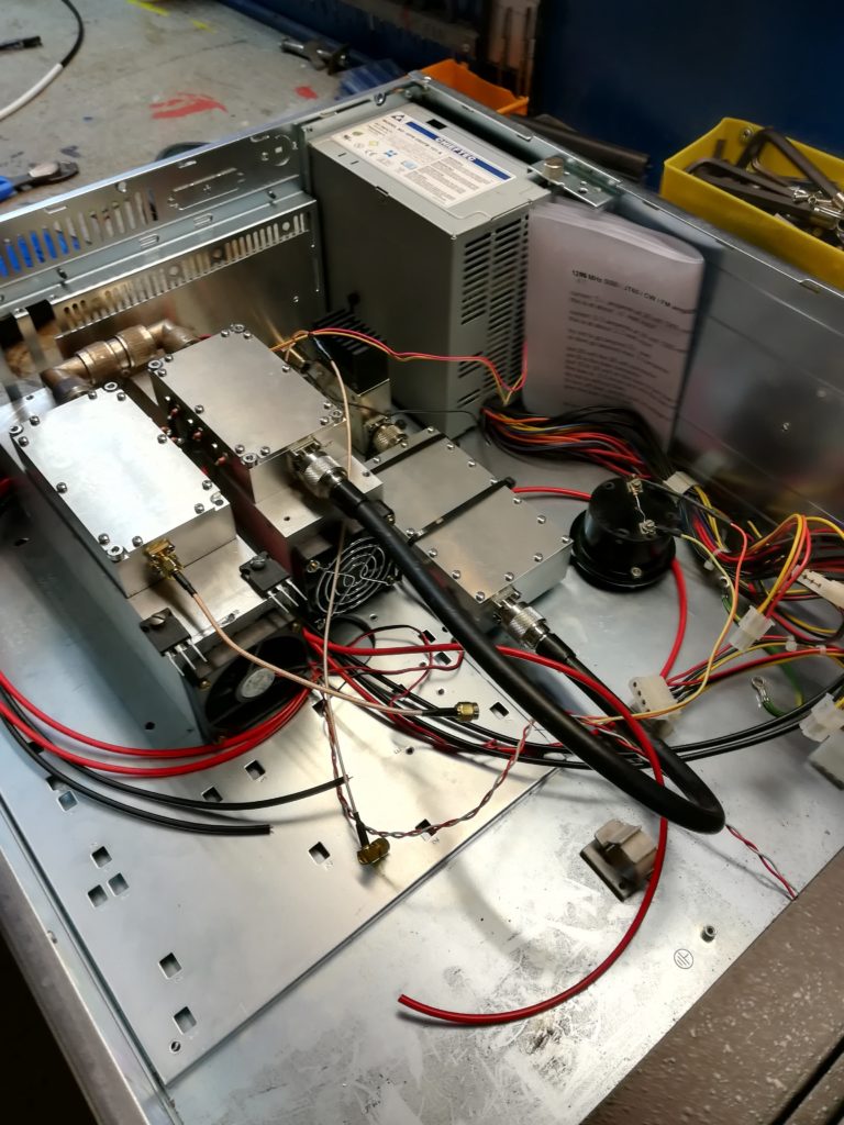
- A view of the completed inside of the LA2SHF beacon.
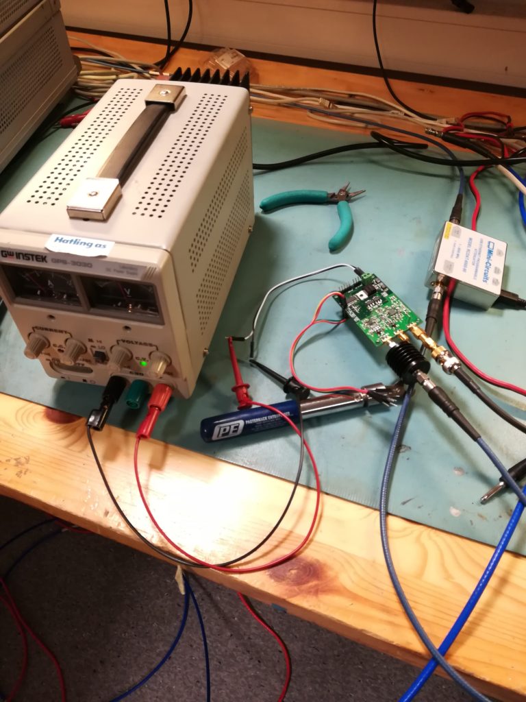
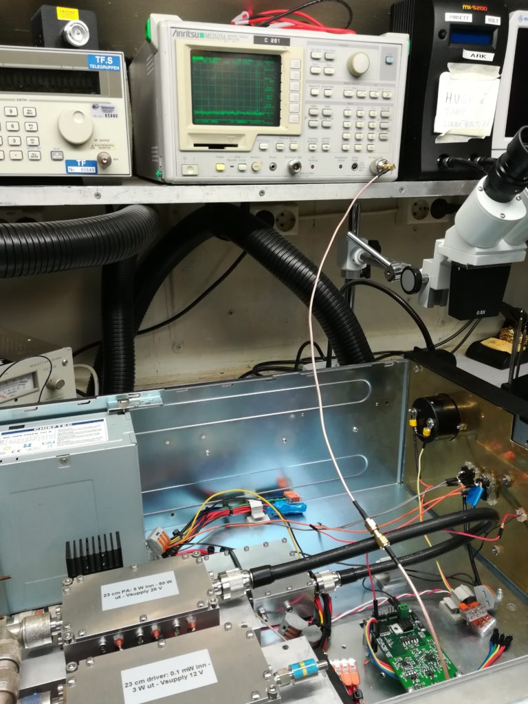
Once the internals were completed it was time to ensure that the beacon would work as intended on the air. First order of business is a test of the amplifiers. To conduct this test a signal generator is used as the exciter for the amplifiers. The output level of the generator was carefully stepped up until the desired amplifier output power was achieved. The corresponding input drive was then measured with a spectrum analyzer.
The output power of the CW beacon PCB is adjustable through the ADL5330 Variable Gain Attenuator (VGA) circuit. By changing line #58 and #64 in main.c this power may be adjusted. We connected the beacon output to a spectrum analyzer and started tuning the power until it was at the level obtained in the previous paragraph. Once these levels were found it was time to investigate that no splatter occured after amplification.
-
- Tuning output power of the CW beacon with a spectrum analyzer.

-
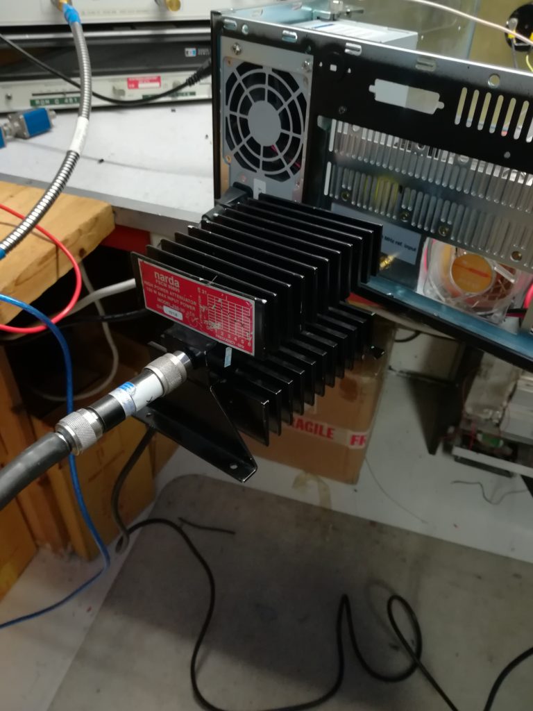
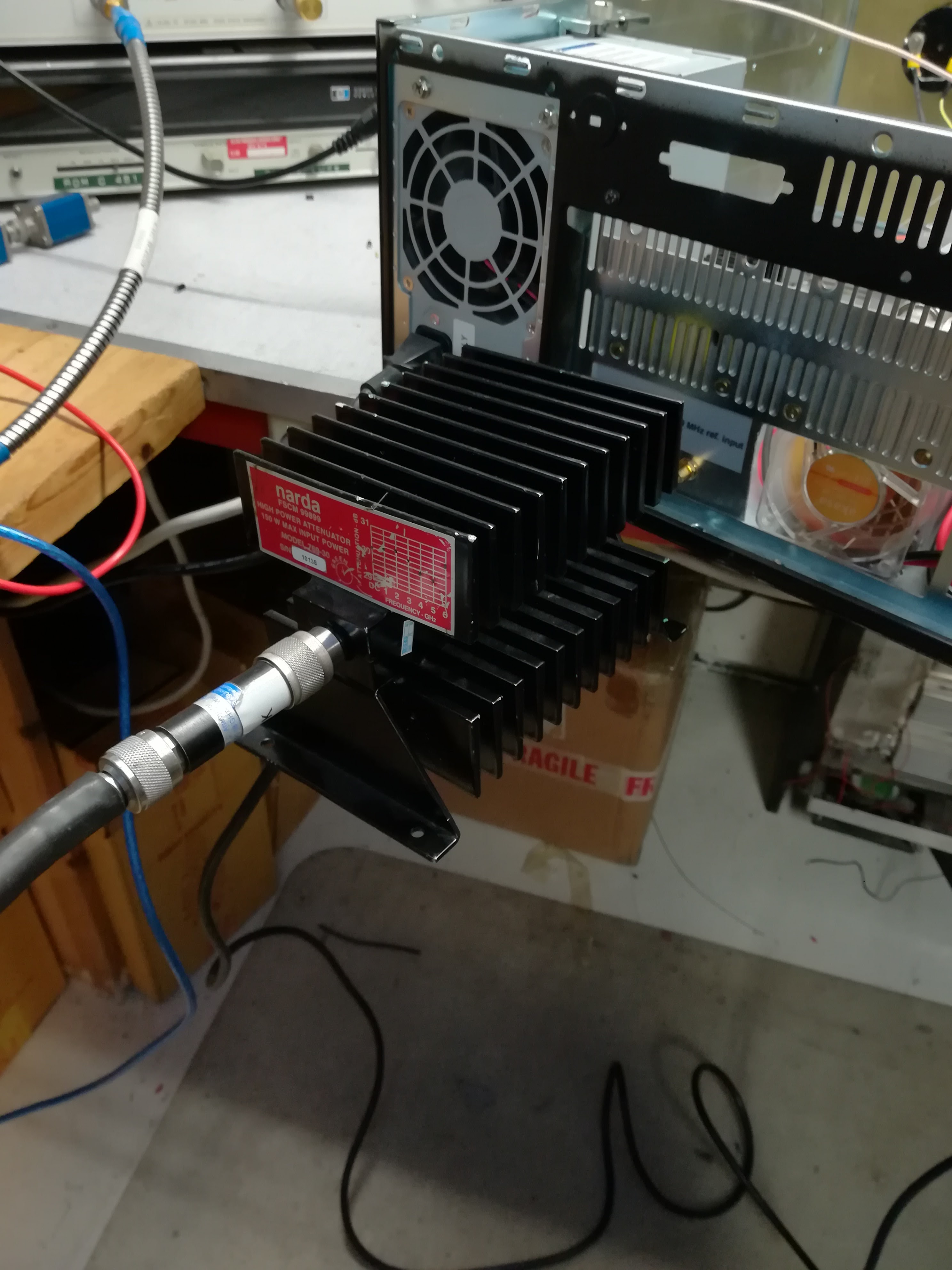
- Measuring on a 75 W (max) requires certain precautions. This is 30 dB 150 W followed by 30 dB 1 W.
-
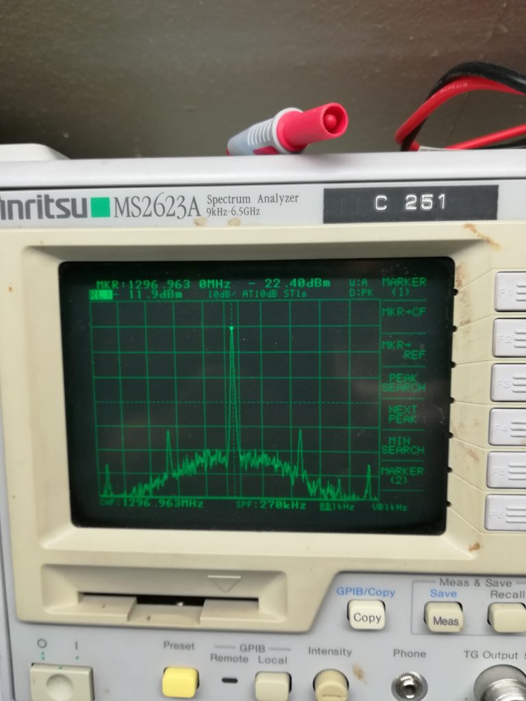
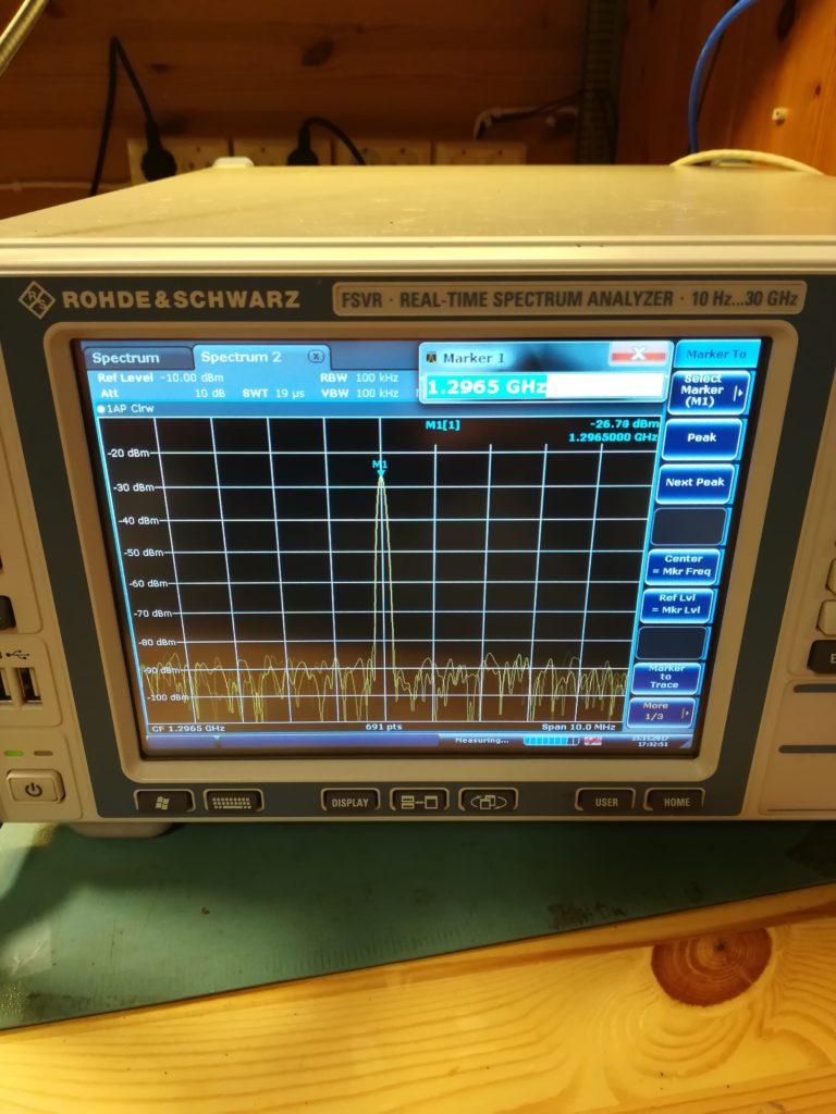
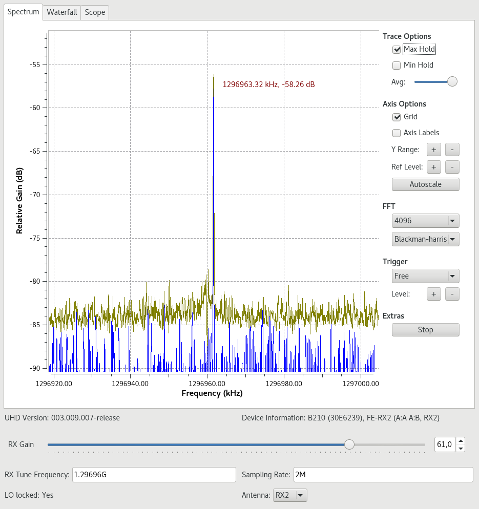
- The spectrum around 1296.963 MHz.

With a relatively clean output signal, and a successful test reception between LA1K at JP53EK and LA1BFAs site at JP53EJ we now have a working beacon!
LA2SHF as received from LA1Ks 3m dish.
It has been very exciting to work on this soon to be 40 year old project. We are on the finish line, all that remains now is to mount it at Vassfjellet. It will be exciting to see how it performs in test operation, and if there are any bugs that need to be ironed out. As a stretch goal we want to make the beacon available on the PI4 digital mode, and are working on the code to do so. For now CW is the main operational mode.
If you are able to hear the beacon, please send us a signal report at la2shf@la1k.no.

Dear Partner:
We are trying to mount a 1296mhz beacon in in53 , after looking for something commercial, we came across your project.
We would like to know if you have any modules for sale
Thank you very much for your attention
Ea1ta
Hi Manuel!
Unfortunately we do not have any modules for sale, but PE1RKI can probably provide the amplifier and filter.
73s de LA3WUA