
In November last year, we were tasked by Orbit to design and build an antenna for their suborbital group. The suborbital team is made up of first-year engineering students working on a balloon satellite, which they plan to send to around 25 km altitude. Last year, ARK also helped with an antenna.
Last year LB5DH and LB7IJ made a simple dipole for this purpose. They used the top section of two glass fiber fishing poles to support two thin wires. This made it relatively lightweight, while also quite sturdy. To bind it together, they 3D-printed a center piece that fit the fishing poles and provided strain relief for the coax. They used a choke balun wound around a small torroid. This project had a relatively fixed scope and reasonable size, so they thought it would be a nice introduction project for new members to get familiar with antenna building.
This year we gathered a bigger team of last autumns recruits to make this antenna. Lots of great ideas came up, and after some discussions we decided we wanted to go for a circularly polarized antenna, since that’s more or less standard for satellite communication where the satellite (or in our case, the balloon) tends to spin or change orientation during flight.
We split into two teams:
- One team would prototype a helix antenna
- The other team would explore a circularly polarized Yagi antenna
Below is a breakdown of the thinking behind each design, and what we had to consider in the early phase.
Design Requirements
Before diving into the antenna types, these were the key constraints we had to keep in mind:
- Frequency: 144.700 MHz
- Weight limit: 100 grams
- Environment: Operates from ground level to ~25 km altitude. Must withstand temperatures down to -56°C
- Should ideally have gain (we want a strong signal)
- Circular polarization preferred (due to balloon rotation)
- Lightweight materials only (aluminum? carbon? 3D print parts?)
- Placement: Mounted on the balloon platform, with limited space
- Ground plane/jording: If needed, can we do artificial ground? What’s the tradeoff?
Antenna Concept 1: Helix Antenna
We originally liked the idea of a helix antenna because it offers:
- High directivity and gain
- Circular polarization
- Theoretically simple structure (wire on a tube)
However, as we worked through the numbers, a few concerns popped up:
- Too directional, might miss the balloon if it drifts off center
- Narrow beamwidth (~50° x 50° depending on turns and diameter)
- Could be physically large (0.5 to 0.9 m long)
- Hard to build accurately, especially with weight constraints
Still, it’s a cool design, and we wanted to test how feasible it is with fewer turns (less directivity) or maybe even try a quadrifilar helix which should offer wider beamwidth and better coverage.
From Plan to Prototype – What We Actually Built
As often happens in student projects, time flew by faster than we expected. We postponed the final decision a bit too long, and suddenly the launch date was right around the corner. That meant we had to move fast and make some compromises.
The First Attempt: Circularly Polarized Yagi (Kind Of)

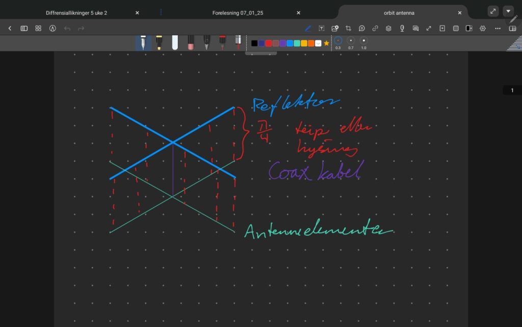
We ended up going with a Yagi-style design, but without the traditional directors. Instead, we built a crossed dipole with a reflector, essentially a basic turnstile antenna. Our goal was to achieve circular polarization by placing two dipoles at 90° to each other and introducing a 90° phase shift between them using capacitors. See Figure 1 for the general layout.
We quickly built a prototype
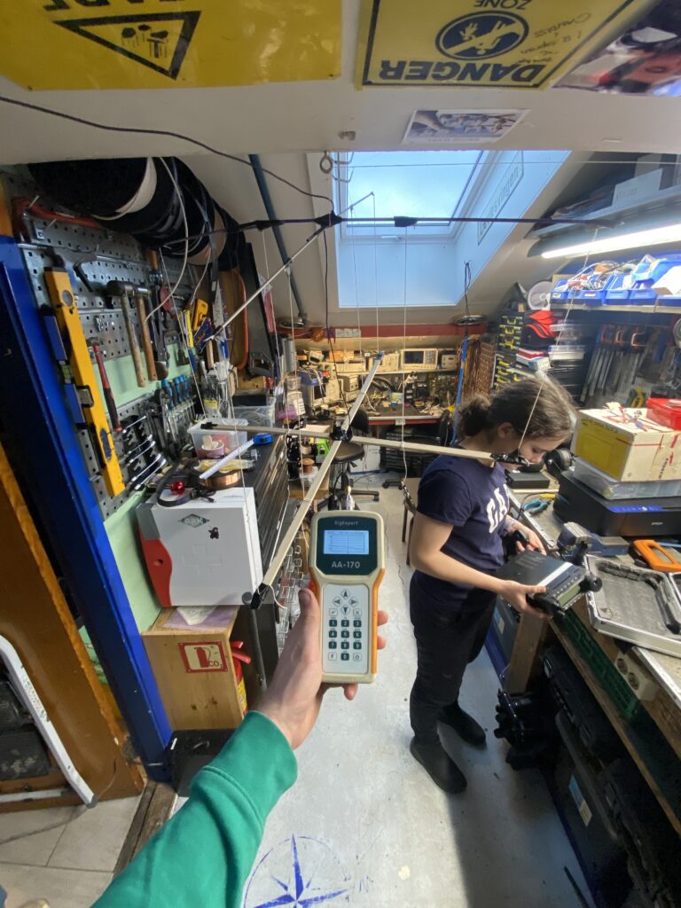
Then we tuned the antenna to get it matched properly for 144.700 MHz, achieving a very low VSWR, which was promising. The antenna was also light, which checked another important box.
Did We Actually Achieve Circular Polarization?
That was the big question.
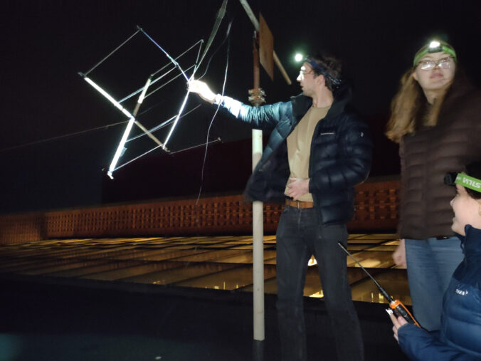
Since we didn’t have access to a proper test setup for polarization, we had to improvise. We added about 80 dB of attenuation, and then transmitted with a walkie-talkie-style antenna on the receiving side. By rotating the receiving antenna and monitoring the signal strength with an old Rohde & Schwarz spectrum analyzer, we hoped to confirm the polarization.
We observed around a 5 dB difference when rotating the receiving antenna, which could indicate circular polarization — but it wasn’t conclusive. It’s genuinely harder to confirm circular than linear polarization with basic tools, so we weren’t fully confident the antenna was working as intended.
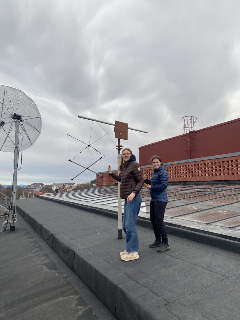
Plan B: Lightweight Dipole with Reflector
Since the circularly polarized prototype was questionable, we decided to go for something simpler and more reliable: a standard dipole with a reflector, sometimes referred to as a “Moxon-like” antenna.
This version dropped the circular polarization goal. Instead, we focused on making it as lightweight as possible. Here’s what we did:
Reflector: Made from old aluminum arrows
Structure: Balsa wood
Elements: Thin copper wire
Support: Fishing line was used to stabilize and hold the structure together

It looked a bit DIY (because it was), but it held up surprisingly well. We didn’t have time to precisely weigh it before handing it off to Orbit, but based on estimates, it came in under 50 grams — which we were pretty proud of. Orbit measured it to be 24.45 grams.
What Happened During Flight?
Well… unfortunately, not much. Orbit had some issues with communications during the mission, so the antenna was never properly tested. It’s also unclear if our antenna was even mounted on the payload. So that part of the project remains a bit of a mystery.
Looking Ahead
Even though this year’s result was inconclusive, I’m definitely coming back to the circular polarization idea next year. There’s something really satisfying about getting it right, and I want to see this design fully working.
To make that happen, I might need to reach out to someone more experienced in RF and antenna design. It’s a tricky problem, and having a mentor or advisor could make a big difference. Either way, we have learned a lot.
Thanks to
- LB2CK
- Emma
- Sven
- Sara
- LB5DH
Written by: LB3CK


Leave a Reply