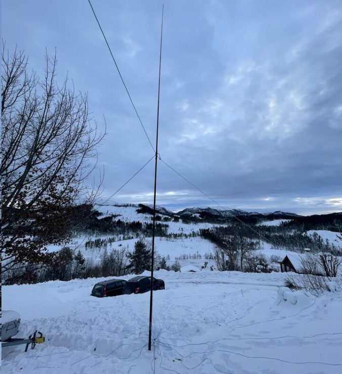
One of the antenna projects that we completed recently is a loaded shortened quarter-wave vertical 80-meter antenna, intended for use on our portable radio trips.

Photo: LB5PI
The plan was the following:
- 12-meter antenna mast
- Antenna element taped to the top of the mast
- Loading coil at the bottom to increase the electrical length
- 16 radials of length λ /10
An antenna mast of 12-meters gives us a resonant frequency too high for the 80-meter band. We, therefore, added a loading coil to the bottom to decrease the resonant frequency, making the antenna operable on the 80-meter band.

Photo: LB5PI
After some research, we chose to have 16 radials as it seems increasing the number of radials beyond this does not give any noticeable difference. Using the ARRL Antenna Book, we found that when using 16 radials, their length should be λ/10.

Photo: LB5PI
We already had a 12-meter Spiderbeam fiberglass telescope pole to use as the antenna mast. We bought a roll of 1.5 mm RK wire to use for the radials and the antenna element.

With: LB8LI, LB0ZI, LB1DJ and a very happy LB0VG! Photo: LB5DH
To make the radials, the wire was cut into 16 equal pieces of 8-meter length and each piece was individually soldered to ring-style crimp terminals. These were then all treaded on a bolt and tightened with a nut, making sure the excess grey-wire for the feed point was left accessible. The wire was then soldered to the shield connection on a chassis-mount SO-239 connector.

terminals from all 16 radials treaded on a bolt (right) via the grey wire
Photo: LB9WI
When measuring out the wire for the antenna element, we realized we didn’t have enough wire left for the planned 12-meter length. However, since we had accidentally cut the wire up for 17 radials instead of 16, we were able to solder together the 17th radial with the remaining wire, cover the connection with a shrink sock and use it for the antenna element.
We initially planned to use a loading coil that we got from LA2QUA, however, the results from using that coil turned out to be very unsuccessful. It was eventually discovered that this coil was coincidentally self-resonating at 3.5 MHz which made it very unsuitable to use as a loading coil for the 80-meter band. Instead, we took some 1.5 mm RK wire and wrapped it around the bottom of the antenna mast 19 times to make a coil.
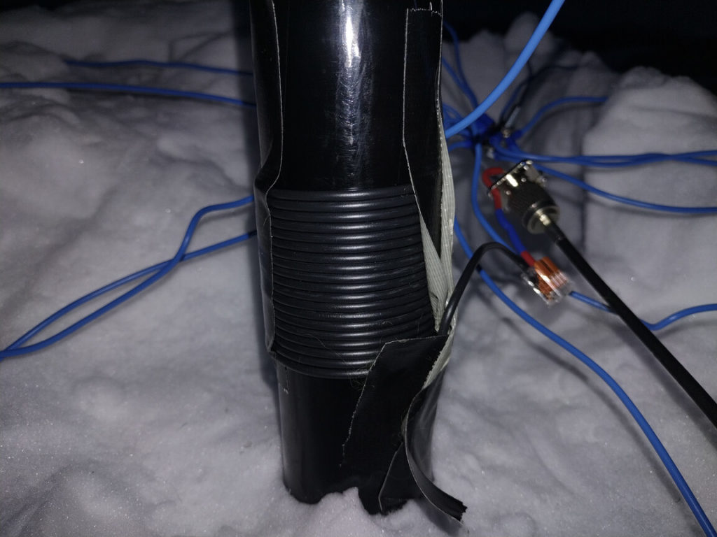
1.5 mm RK wire wrapped around the antenna mast
Photo: LB5DH
When the finished antenna was all set up, initial measurements from the antenna analyzer showed a very high SWR. We tuned the antenna using an MFJ-948 antenna tuner which brought the antenna closer to 50 ohm.
We used LB0VG’s Yaesu FT-450D radio with the aforementioned tuner and managed to successfully check into QST-LA using our new antenna.
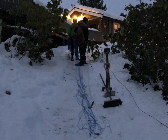
With: LB5DH, LB9WI and LB1DJ
Photo: LB5PI
All in all, we deem the project a success and can’t wait to easily get on the 80-meter band when going on portable trips out in the woods! This project was completed by LB5DH, LB5PI and LB9WI with LA2QUA as a very engaged consultant.


Hi guys!!
Very interesting indeed. I want to look into replicating this for use with my camper/RV because 80m seems to be so unusual to come up with anything usable.
KC0NIB