Since Norway became the first country to shut down the FM-broadcast service (in favor of a nationwide DAB/DAB+ service) there have been a lot of media attention on noise from LEDs interfering with DAB reception. Seemingly in response to this, Biltema, a Scandinavian car centric hardware store, has started stocking an EMC-filter for dealing with LED noise.
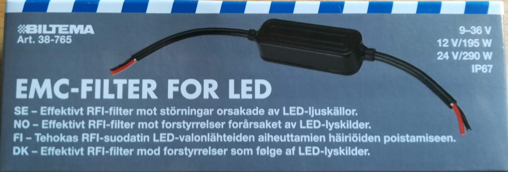
As radio amateurs, it is always useful to have immediate access to parts to help solve various problems that arise. A good DC line filter can allow us to suppress interference, and perhaps be able to use equipment that we previously would have had to turn off in order to make contacts.
So what is it?
Biltema is known to stock white-label products, and the details on general consumer electronics can be a bit lacking. Therefore, we decided to do the only natural thing: buy one and tear it apart.
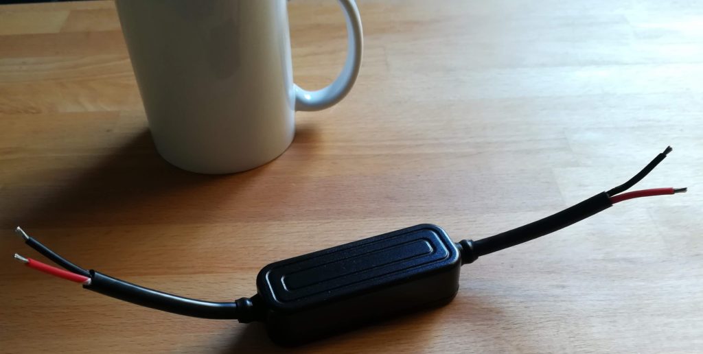
From the packaging and the short webpage description, we know that it is supposed to have the following specifications:
- Voltage range: 9 – 36 V
- Power handling: 12 V : 195 W / 24 V : 290 W
- Dust/water-ingression: IP67
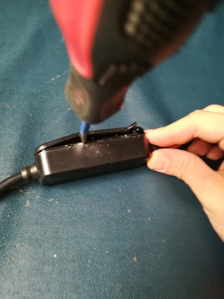
Some force needed. 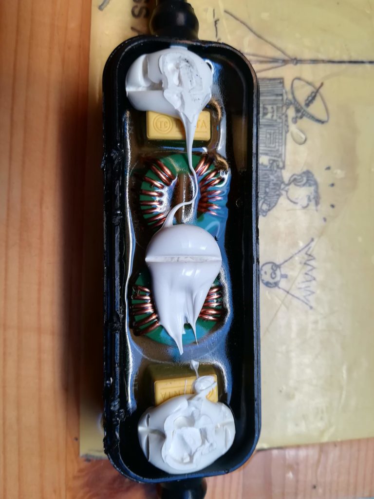
Lid removed, PCB with parts coated in epoxy. 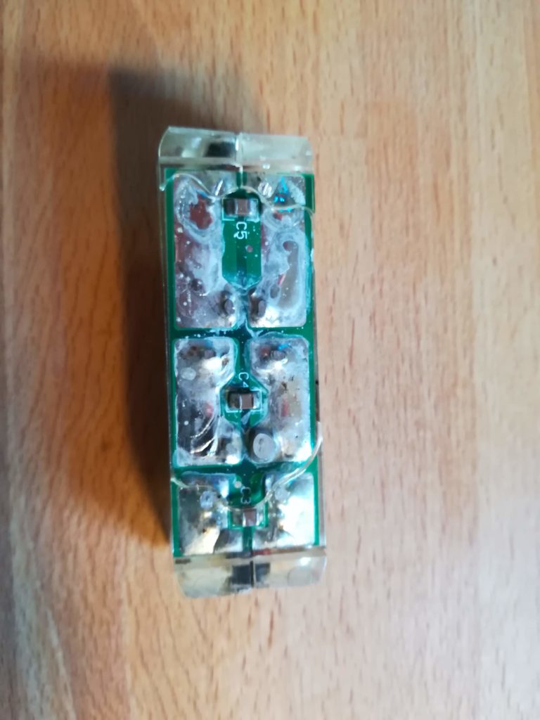
Epoxied PCB removed, underside visible.
We were able to discern the topology after releasing the filter from it’s plastic/epoxy prison. It is a fairly straight forward combination of capacitors and common-mode chokes. Due to the epoxy, we were only able to free the bottom side SMD capacitors from the PCB. Therefore, we were unable to find which exact values had been used for the rest of the filter. Schematically, the filter looks like this:
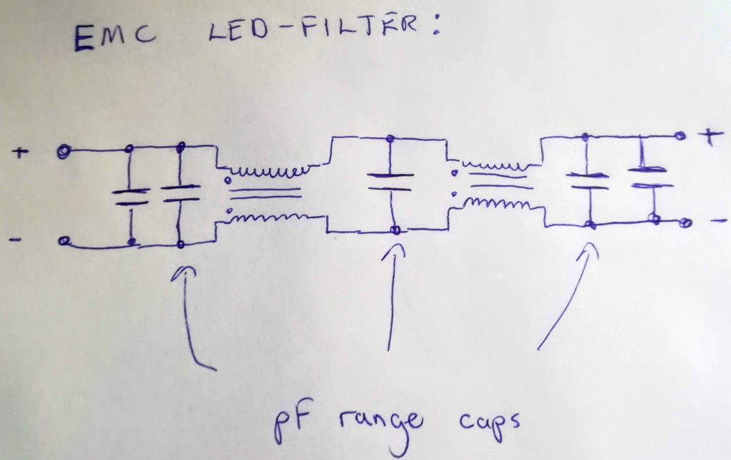
The topology will short high frequency differential mode noise through the capacitors, and prevent common mode noise through the chokes. Using different kinds of capacitors in parallel is a well known technique, which utilizes each capacitor’s frequency response to maximize attenuation/decoupling over a wide frequency range.
How does it perform?
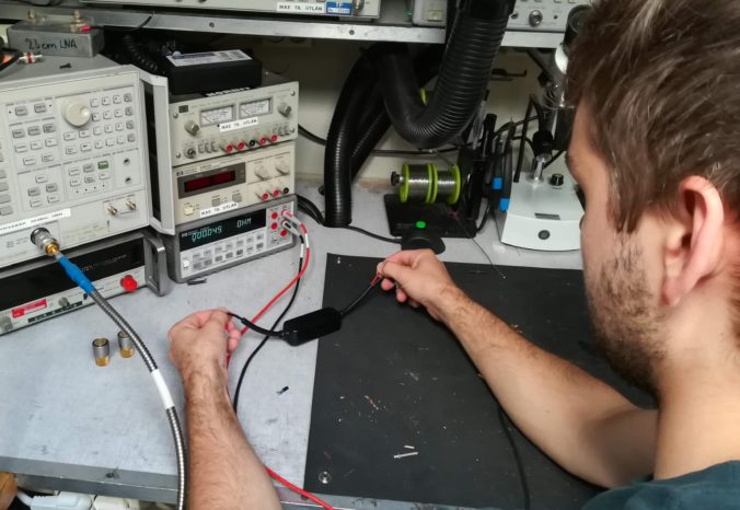
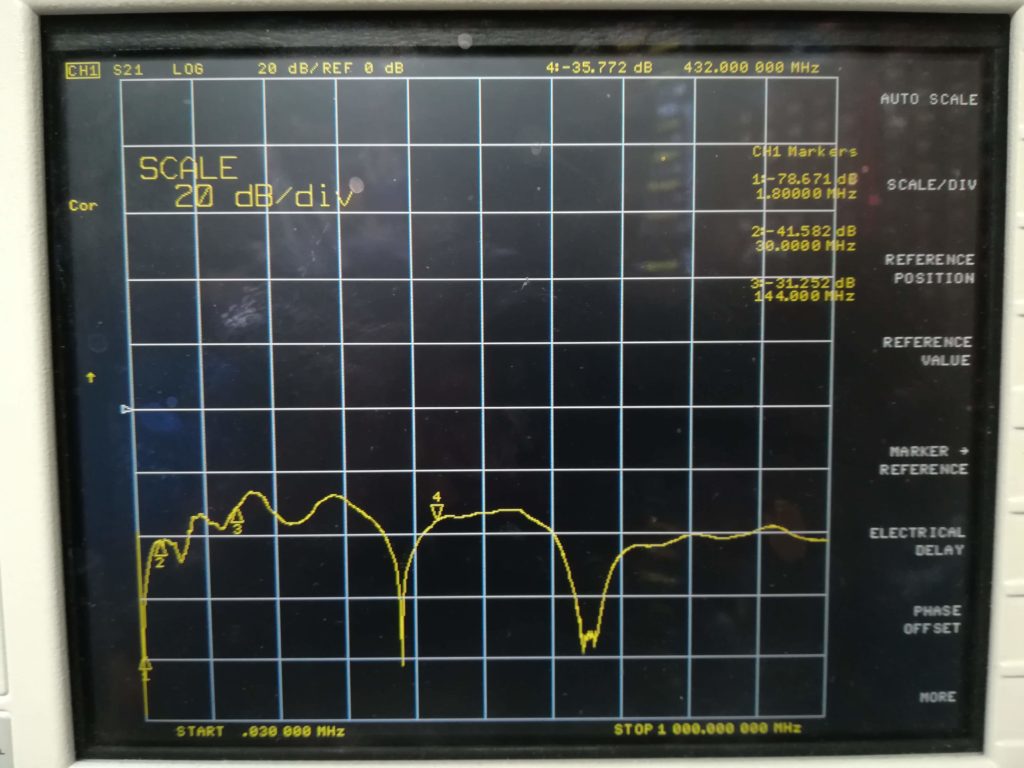
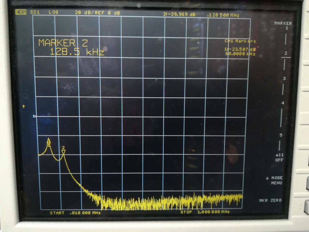
Before breaking open the filter, we also took the time to do some electrical measurements on it. First, we checked the attenuation in a 50 ohm system, to see how much interference reduction would be possible.
The results are very promising, with decent high frequency attenuation, and excellent switch-mode frequency attenuation.
With a multimeter, we also measured the DC resistance, which seems to be on the order of 15 mOhm on our sample.
If necessary, it would also be possible to mix and match these filters in parallel and/or series in order to achieve the desired power handling or attenuation. The voltage should be kept below the recommended 36 V, though, as the capacitors will have a finite voltage rating (probably 50 V).
Overall, we are happy to have found a decent product. This should come in handy the next time we go on a noise hunting adventure. One of these at the power input of a troubled transceiver might also do wonders. This filter will also definitely pack more punch than the typical ferrite clamp filter.

Hello
Are the values of the capacitors known?
Could the filter be used in the AC power line of a vintage tube receiver when the filter would be fitted with caps for higher voltage?
Or in the HT-line?
73 de Henk – Parasetguy – NL13265
Hi Henk!
Apart from the capacitors marked “pF range” in the drawing the values of the capacitors are not know. We were not successful in extracting the capacitors from the epoxy without damaging them, so unfortunately we do not have any values to share.
In principle the filter could be used with modified capacitors, but I believe that it would be difficult to perform the modification due to the need to remove epoxy. I guess it could be done by using a solvent that is PCB-safe, but will dissolve epoxy.
73s de Øyvind/LA3WUA
Thank you Øyvind for your swift answer.
73 de Henk