
We’ve been planning to set up a receiver for ADS-B at Vassfjellet for some time, and after after the upgrade of our 5 GHz link, the time has come to finally do something about it.
Automatic Dependent Surveillance Broadcast (ADS-B) is a service that is required onboard planes above a certain size. We’re already running a receiver at Samfundet (JP53ek) powered by an RTL-SDR and dump1090. This setup is giving us around 180 nautical miles in maximum reception distance (according to fr24 receiver statistics). We’re hoping to improve this by installing another receiver at Vassfjellet, which is at over 700 m above sea level. The setup for Vassfjellet will consist of the following parts:
- Raspberry Pi
- RTL-SDR
- 1090 MHz collinear antenna purchased from eBay.
- 1090 MHz bandpass filter purchased from eBay.
- LNA4ALL
We had the opportunity to go a little overboard with the measurements of the setup: both horizontal and vertical antenna pattern, S-parameters, noise figure and gain were measured. Many thanks to Jens (LB6RH) at the Department of Electronic Systems for helping us measure the antenna in the anechoic chamber at NTNU.

Antenna mounted vertically in chamber.

Radiation pattern of antenna mounted vertically.
The figures above show the mounting position and the measured antenna pattern for the vertical plane. We can see that the antenna performs excellently with an almost omnidirectional pattern.
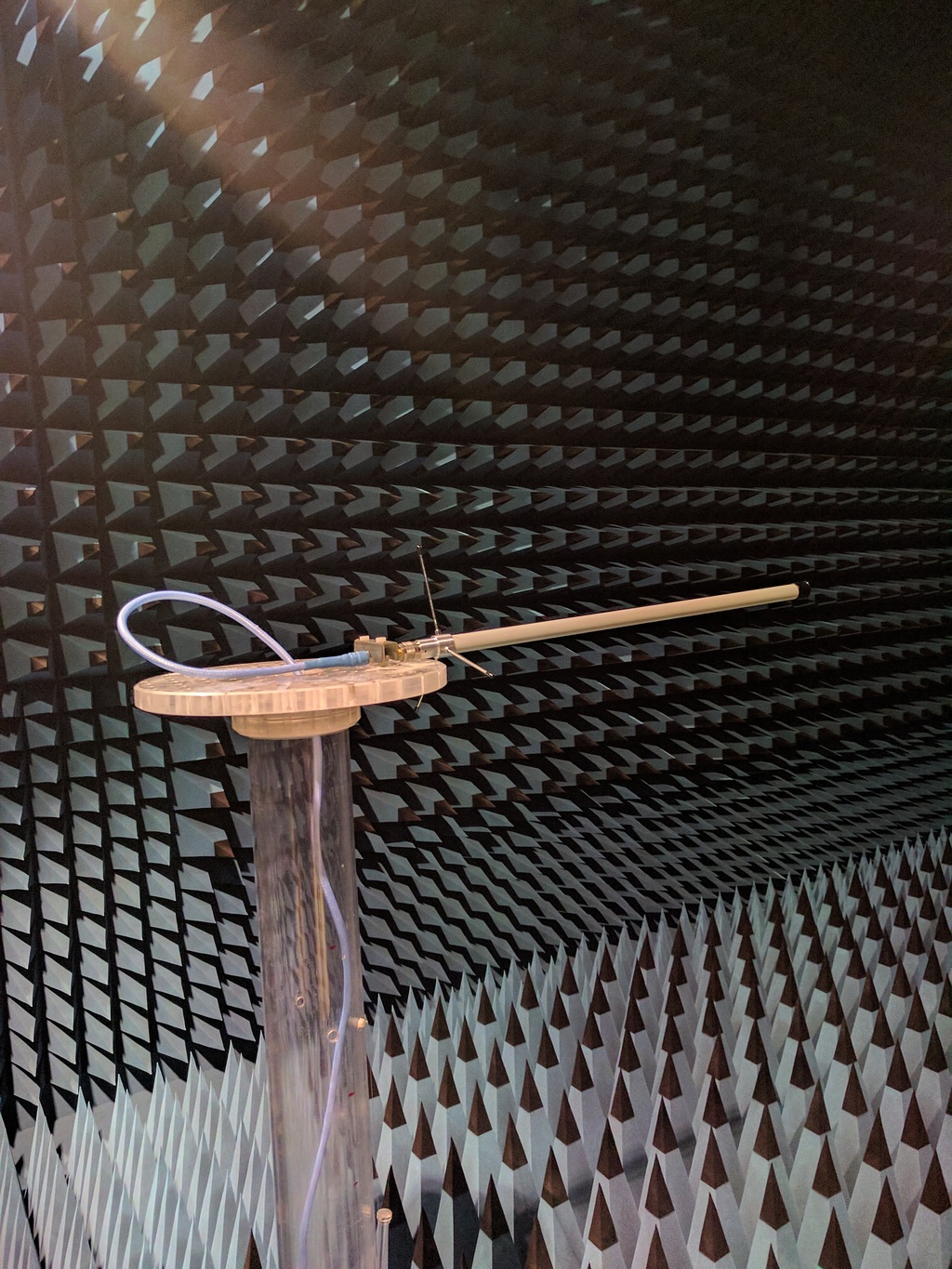
Antenna mounted horizontally in chamber.

Radiation pattern of antenna mounted horizontally. The diagram is oriented so that 0 degree corresponds to the colinear antenna pointing straight towards the reference antenna.
To assess the take off angle of the colinear antenna we mounted it horizontally and changed the reference antenna to a horizontal configuration. The results and mounting position can be seen above. The large lobes at 80 degree and 270 degree correspond to elevation angles 10 and 0, respectively. This means that the horizon is well illuminated and that we will have good reception for multiple planes. Further we see that the sidelobes are more than 10 dB below the main lobes, ensuring that the antenna has good gain.

Filter insertion loss.
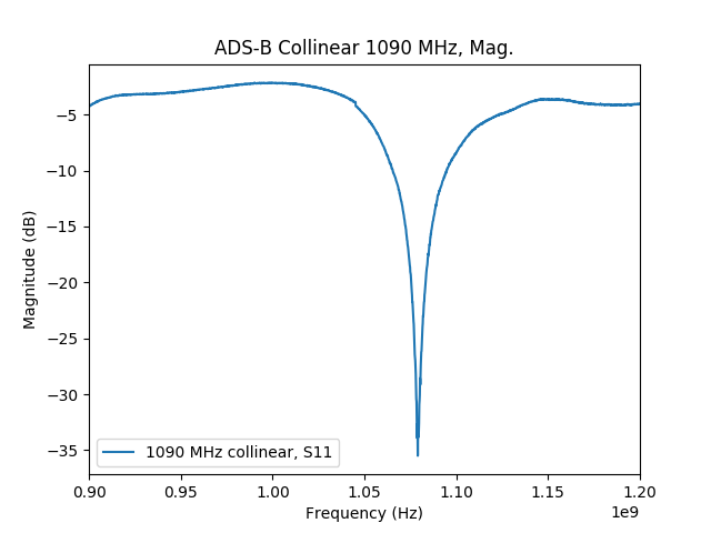
Colinear antenna return loss
The S-parameters for filter and antenna were measured using a miniVNA Tiny and are displayed in the figures above. The performance of the filter and antenna are similar to what their manufacturers claim.
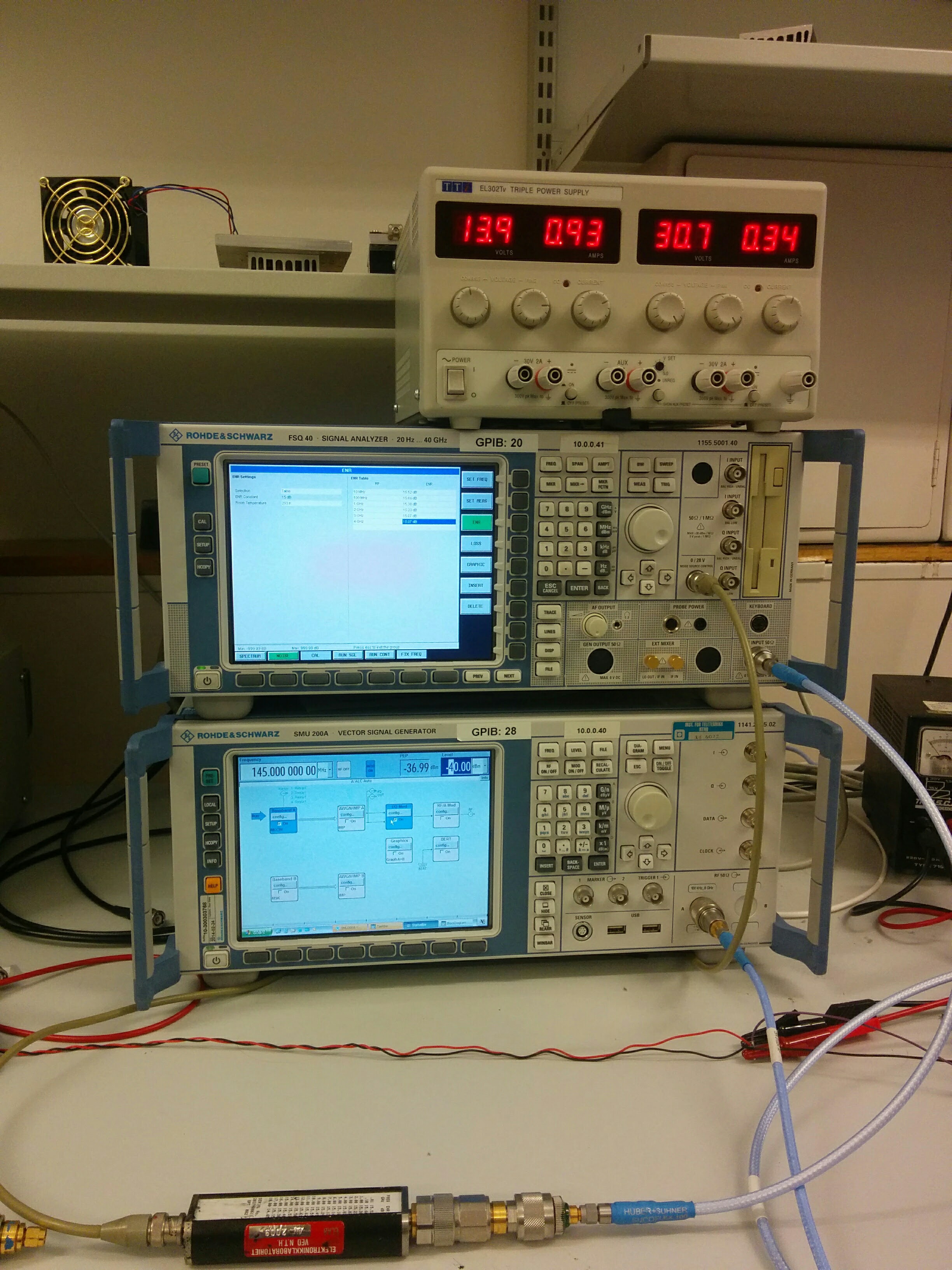
Measurement setup for Noise Figure and Gain measurements.
The next measurement shows the measured noise figure and gain of the LNA4ALL. This was done using the FSV-K30 option on a R&S FSQ signal analyser with a HP 346B noise source, as seen in the figure above. We will get back to this measurement in a separate blog post.
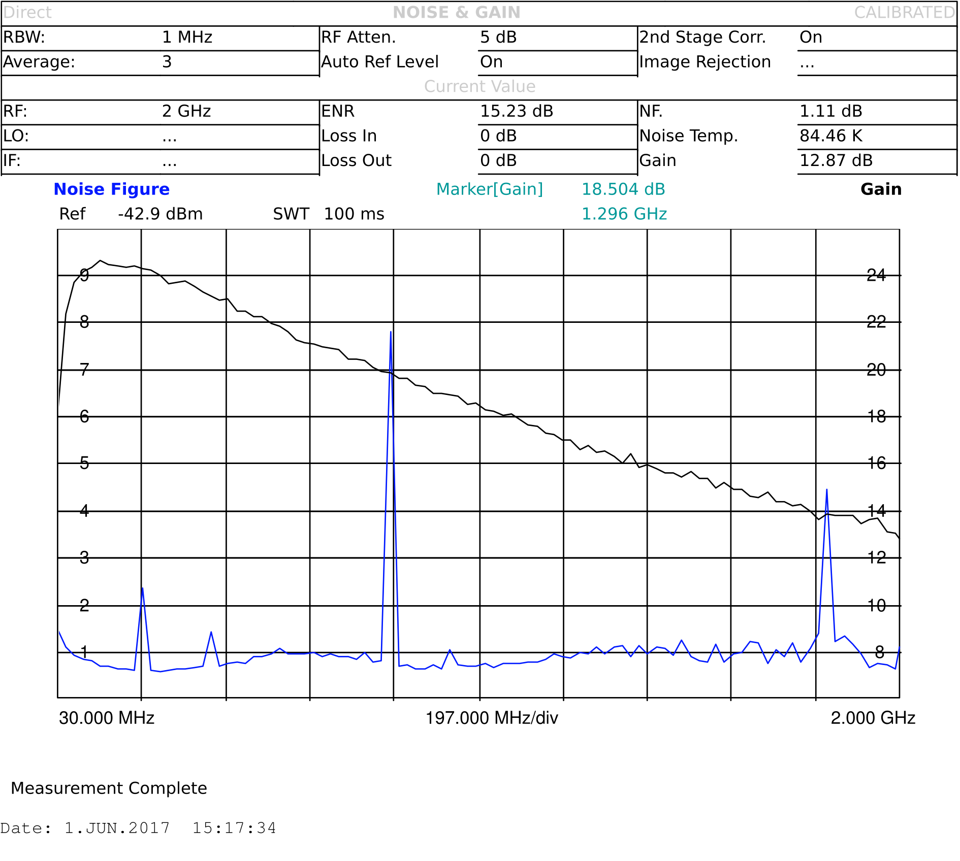
Measured noise figure (blue) and gain (black) for an LNA4ALL
We are very satisfied with these measurement results, and look forward to seeing how the equipment will perform once installed at Vassfjellet. We hope to be able to receive many planes.


0 Comments
3 Pingbacks