During last autumn, we helped LA1NGS change their rotor, and scored their old, broken rotor as “spoils of war”, as LA3WUA put it. Fixing it allowed us to re-use it for our own SatNOGS station, which we have written about in an earlier blog post.
SatNOGS is a global network of satellite ground stations. Users can schedule satellite observations across the globe, and anyone can make use of the data, enabling nice and free information exchange for research and experimentation. Everything is also open source! LA1K is very proud to be a part of this network, and make our location and equipment available for others to use. It also gives us a very convenient interface for making our own observations.
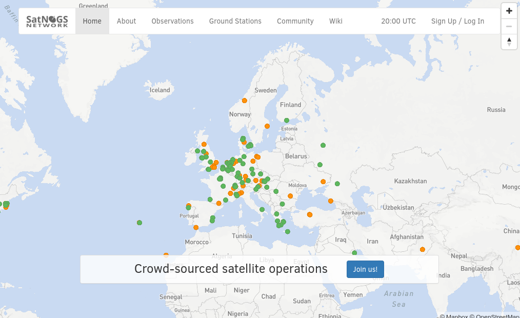
SatNOGS ground station network. 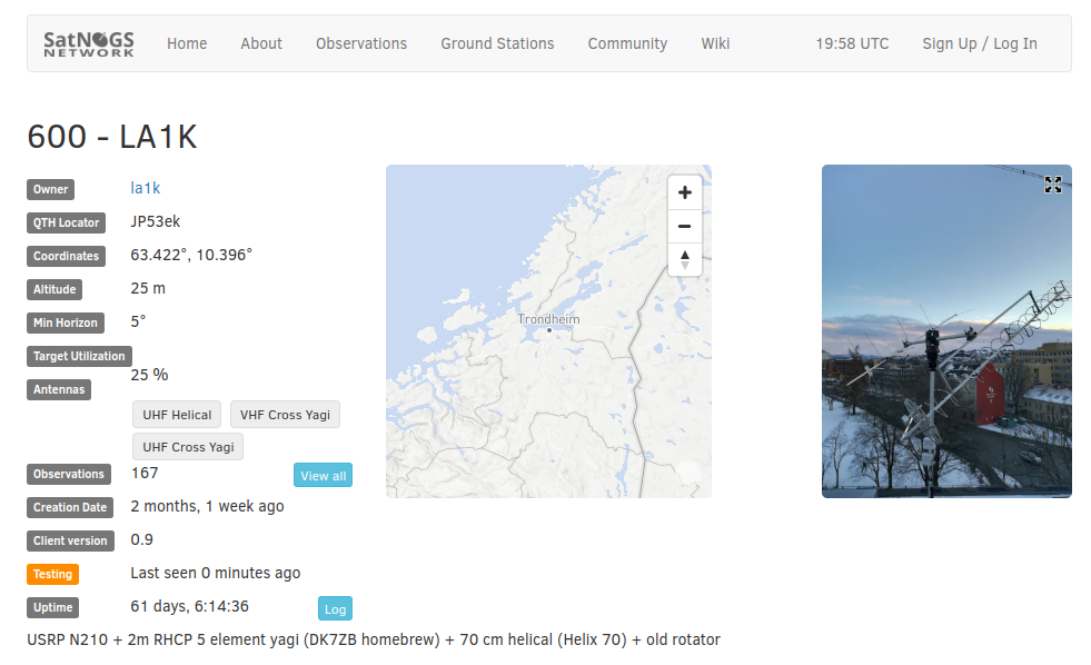
LA1K’s SatNOGS page.
The effort needed to set up a new SatNOGS station can be everything from trivial (enable SatNOGS on an existing station) to slightly non-trivial (build everything from scratch!!!). In our case, we wanted to set up a brand new station with a new antenna, to be smaller and lighter than our rather large and bulky 2m satellite array.
We want to show the work effort behind this and some of our design choices through a series of blog posts, starting with the antenna. The overall work here is also a nice example of the effort involved in setting up a new antenna on the roof of Samfundet.
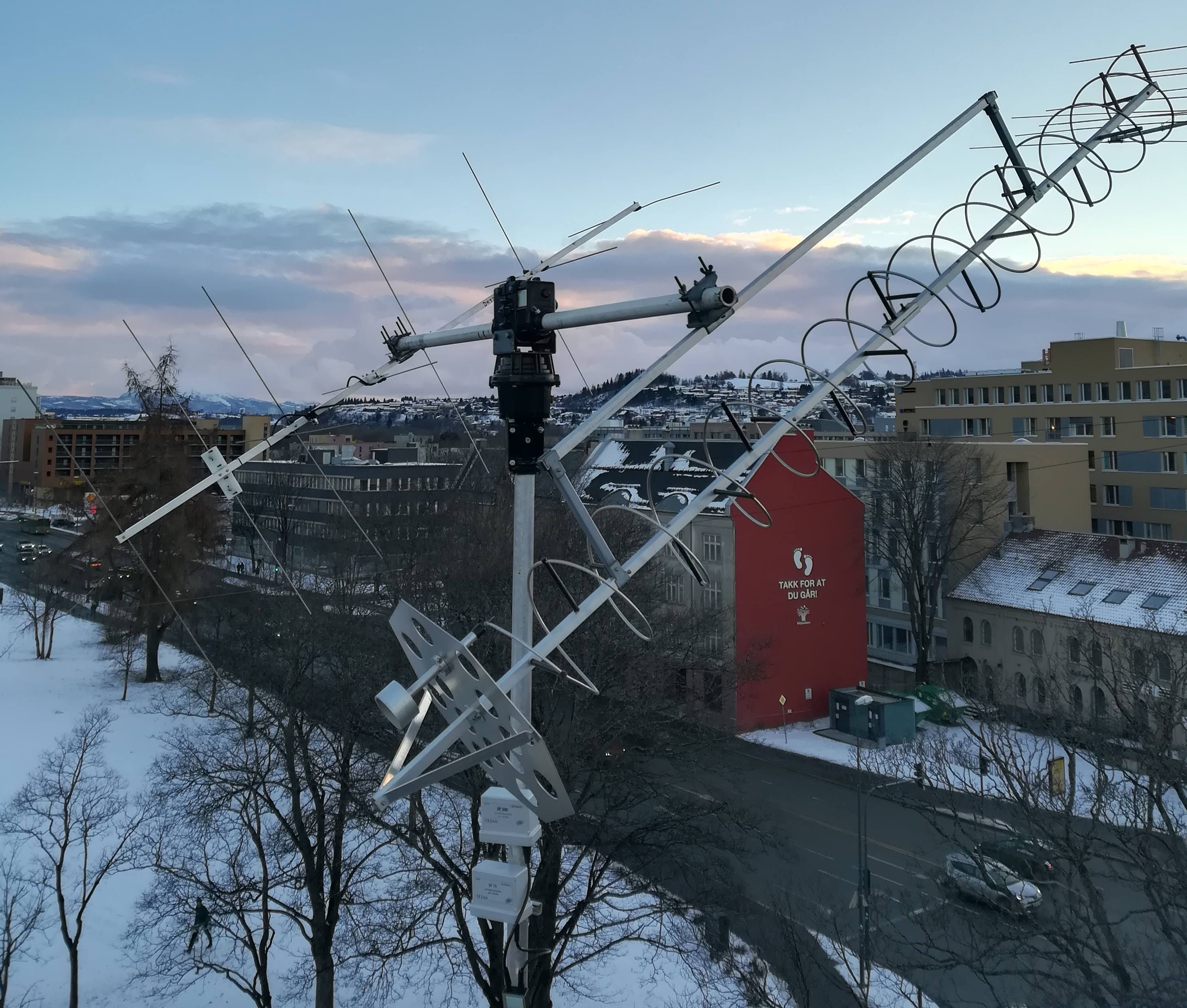
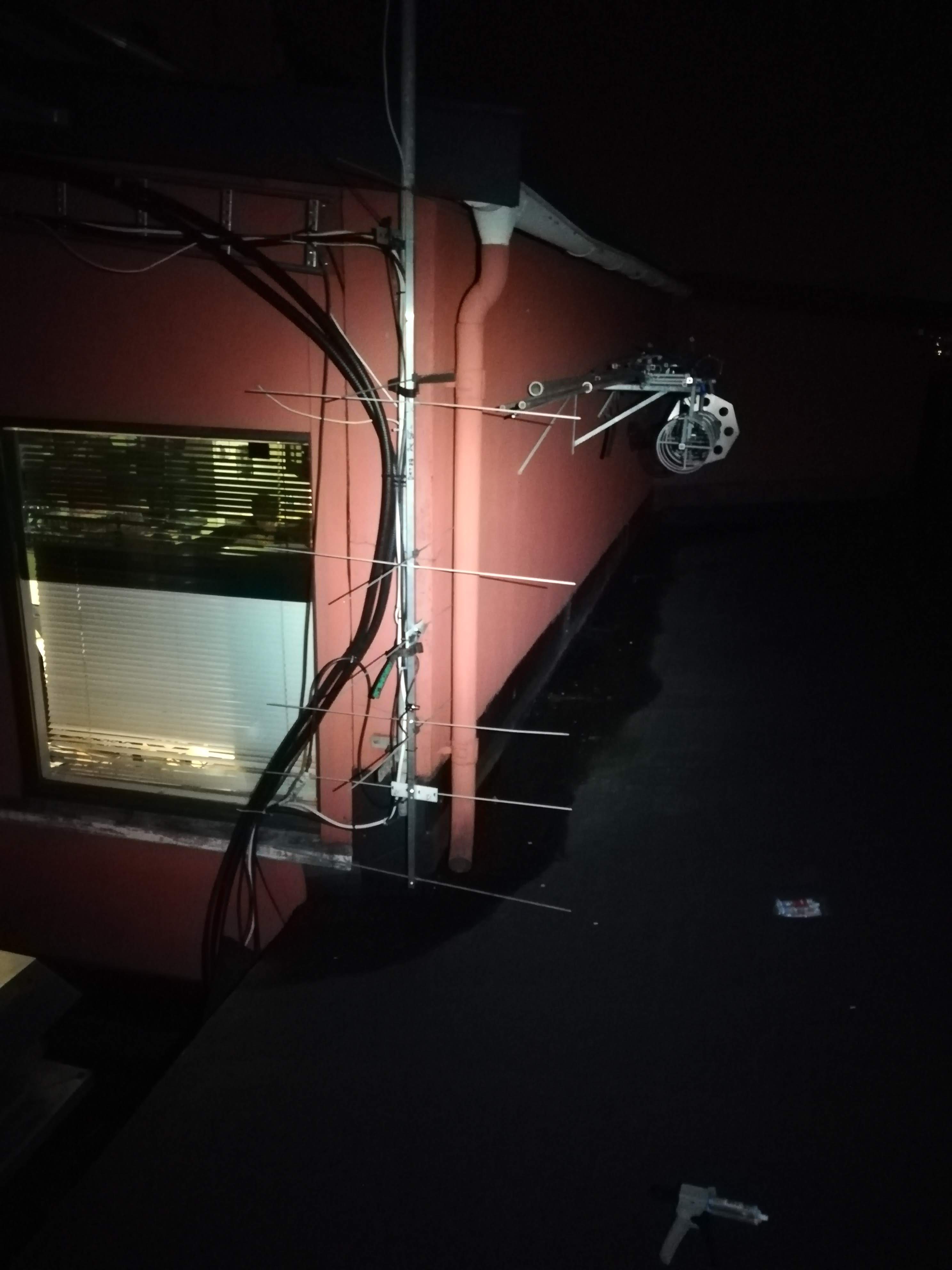
Our SatNOGS antenna system consists of two antennas mounted on the same rotor: one for the 2m band (Yagi antenna, back) and one for the 70cm band (helix antenna, front). The antenna for the 70cm band was pilfered from the satellite array, as depicted below.
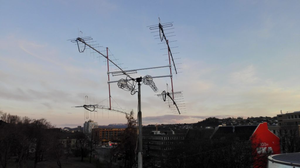
2m/70 cm array previously. 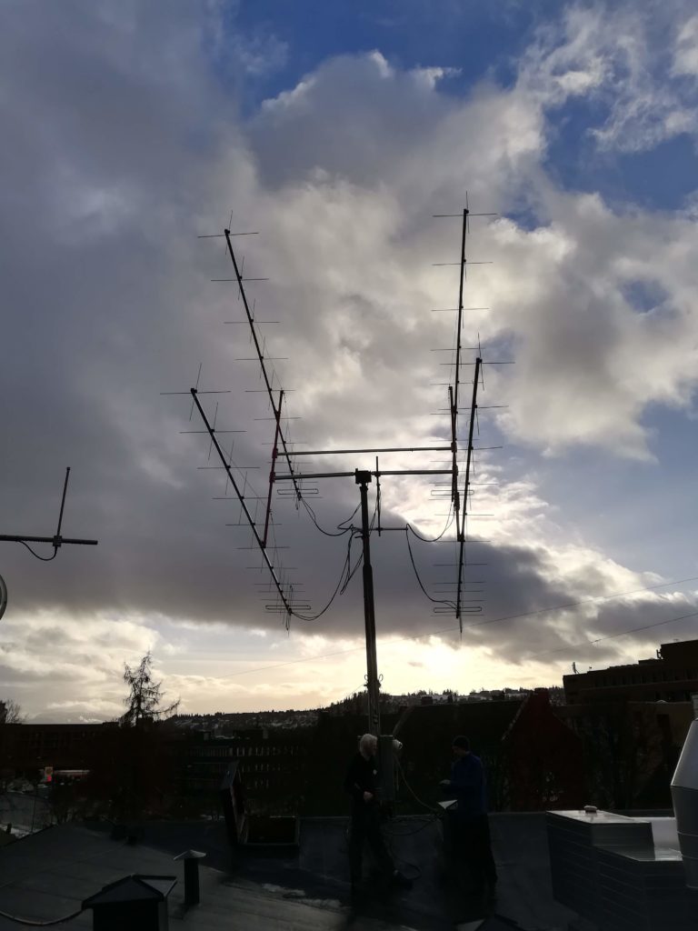
2m array after pilfering.
The 2m antenna was developed from scratch, using DK7ZB’s excellent 2m Yagi recipe – which is the main focus of this blog post.
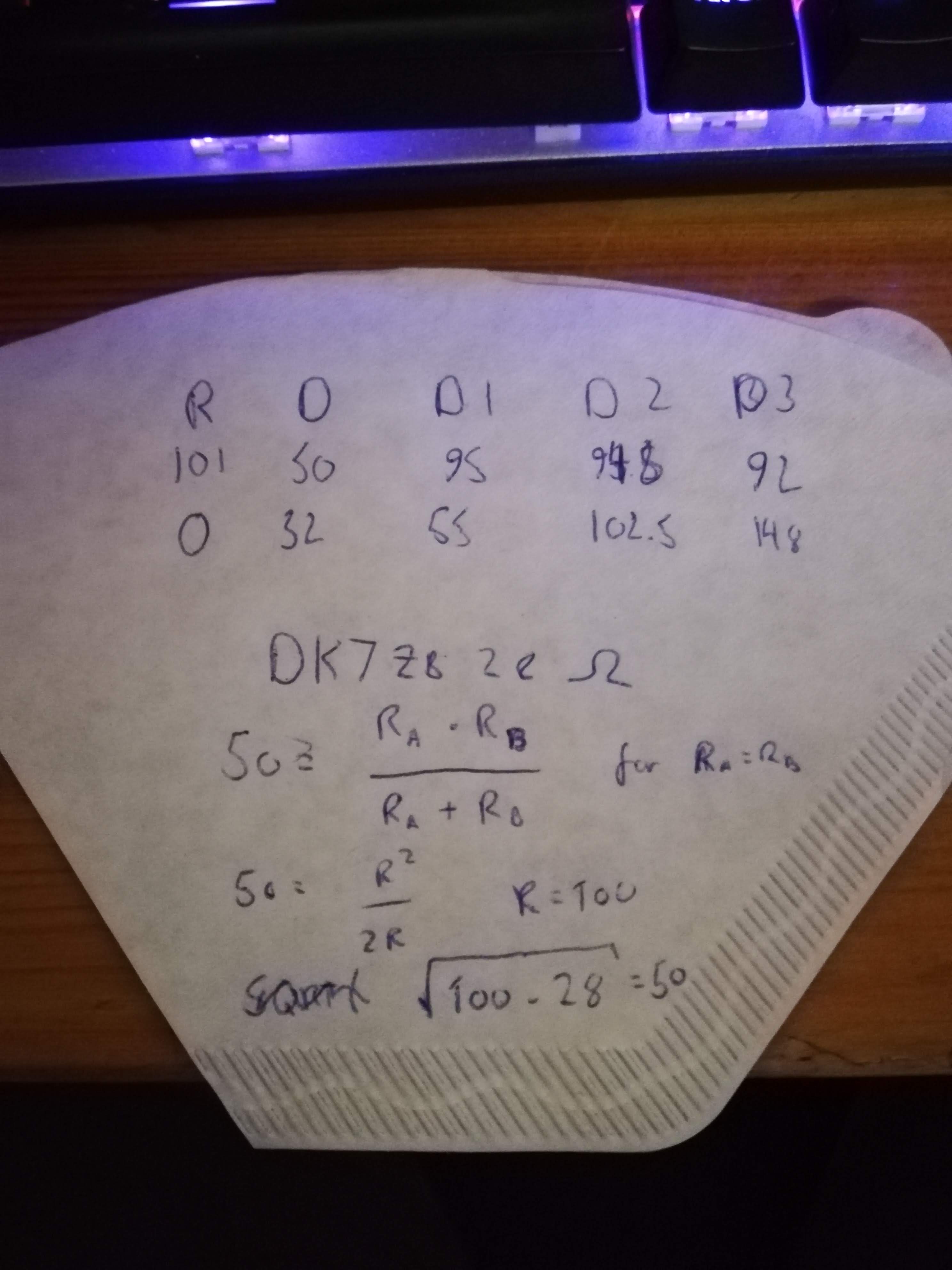
Our antenna consists of two such DK7ZB antennas oriented perpendicular to each other, in order to enable the full system to support circular polarization. One sub-antenna was placed in front of the other, with a distance that corresponds to a quarter wavelength.
Connecting the antennas with a phasing harness consisting of two equally long 50 Ohm cables lets us achieve two things: – the already introduced circular polarization, through the 90 degrees phase shift, and an impedance of 50 Ohm. The antenna is 28 Ohm, but transforming it by a quarter-wave 50 Ohm cable nets us 50 Ohm. This antenna design therefore gives us two nice properties almost free of charge.
The building of this antenna is told through wild (peer-reviewed) extrapolation from the photos LA3WUA has made available to the post author:
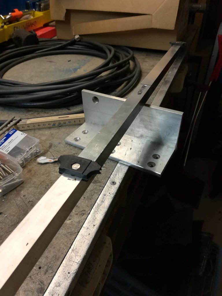
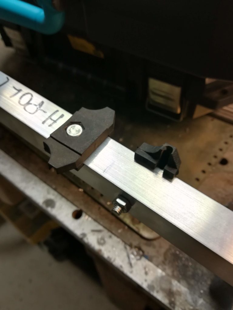
A metallic boom was acquired and drilled, and plastic fasteners for the antenna elements were screwed into place.
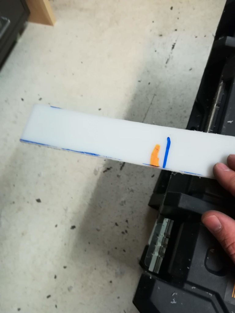

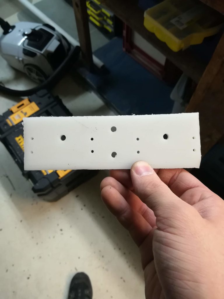
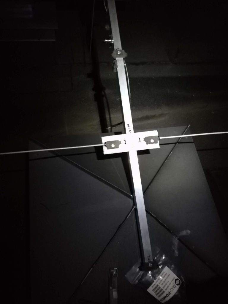
The mount for the driven element was manufactured out of a piece of white plastic, drilled with appropriate holes for mounting.
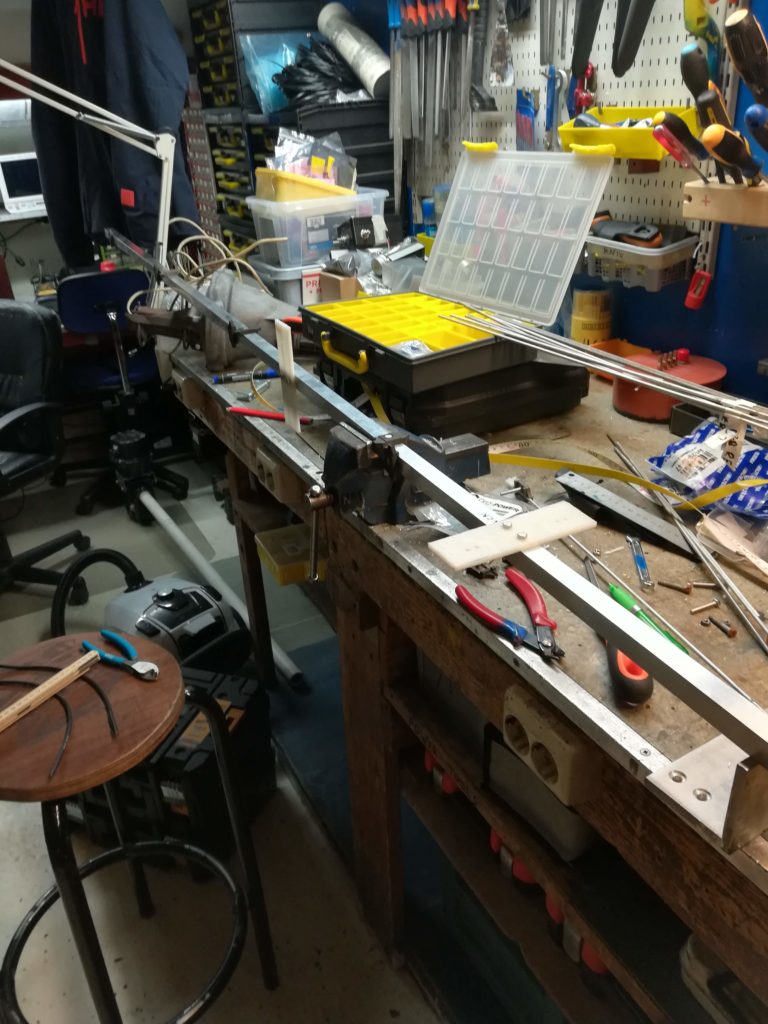
Mounting plate mounted onto antenna boom. 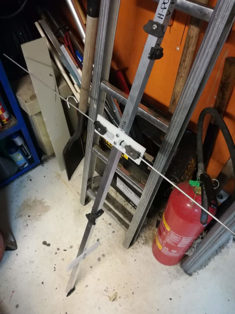
Driven element mounted to plate.
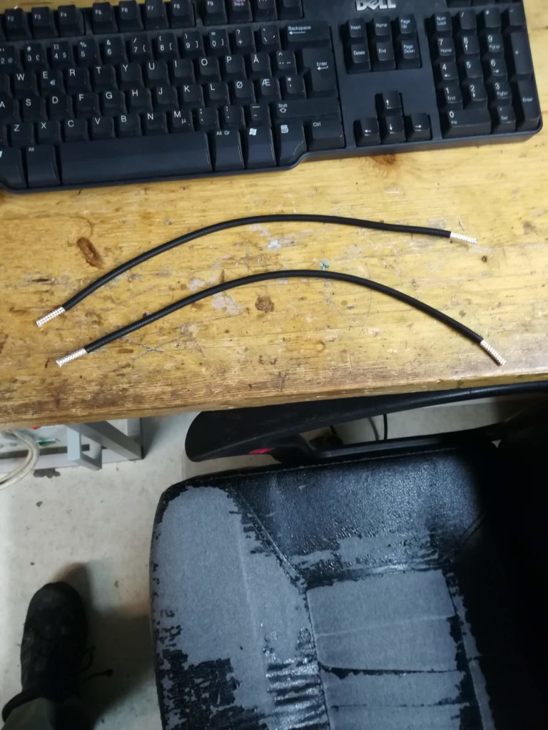
Phasing harness for the driven elements. 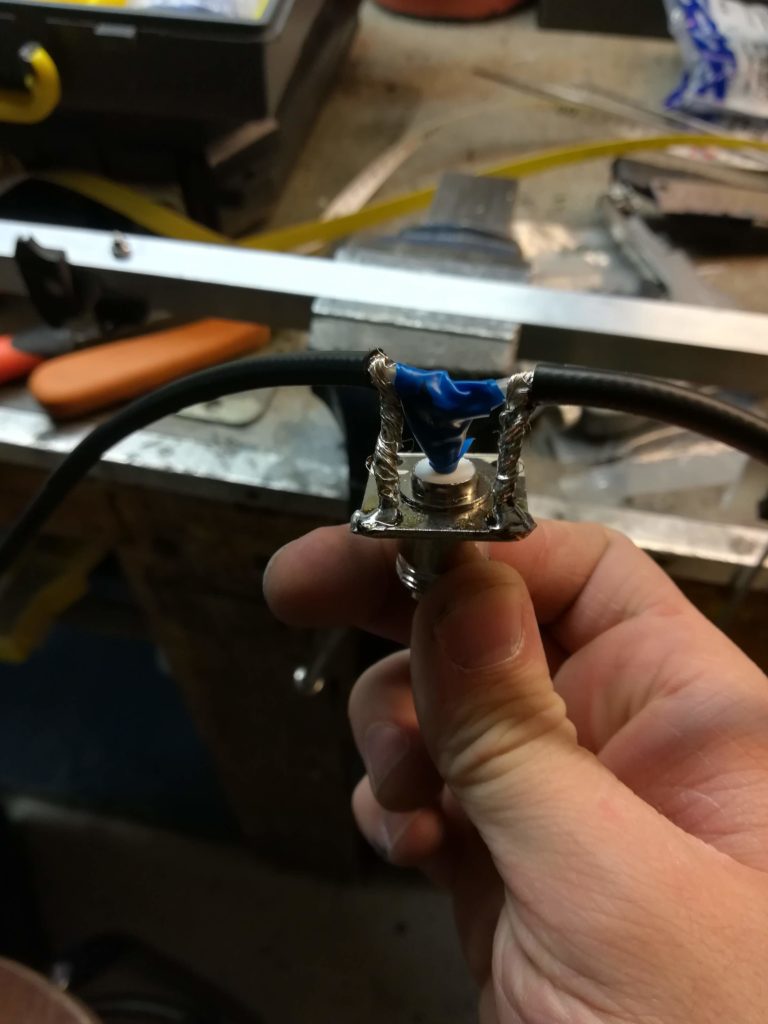
Phasing harness soldered onto coax connector.
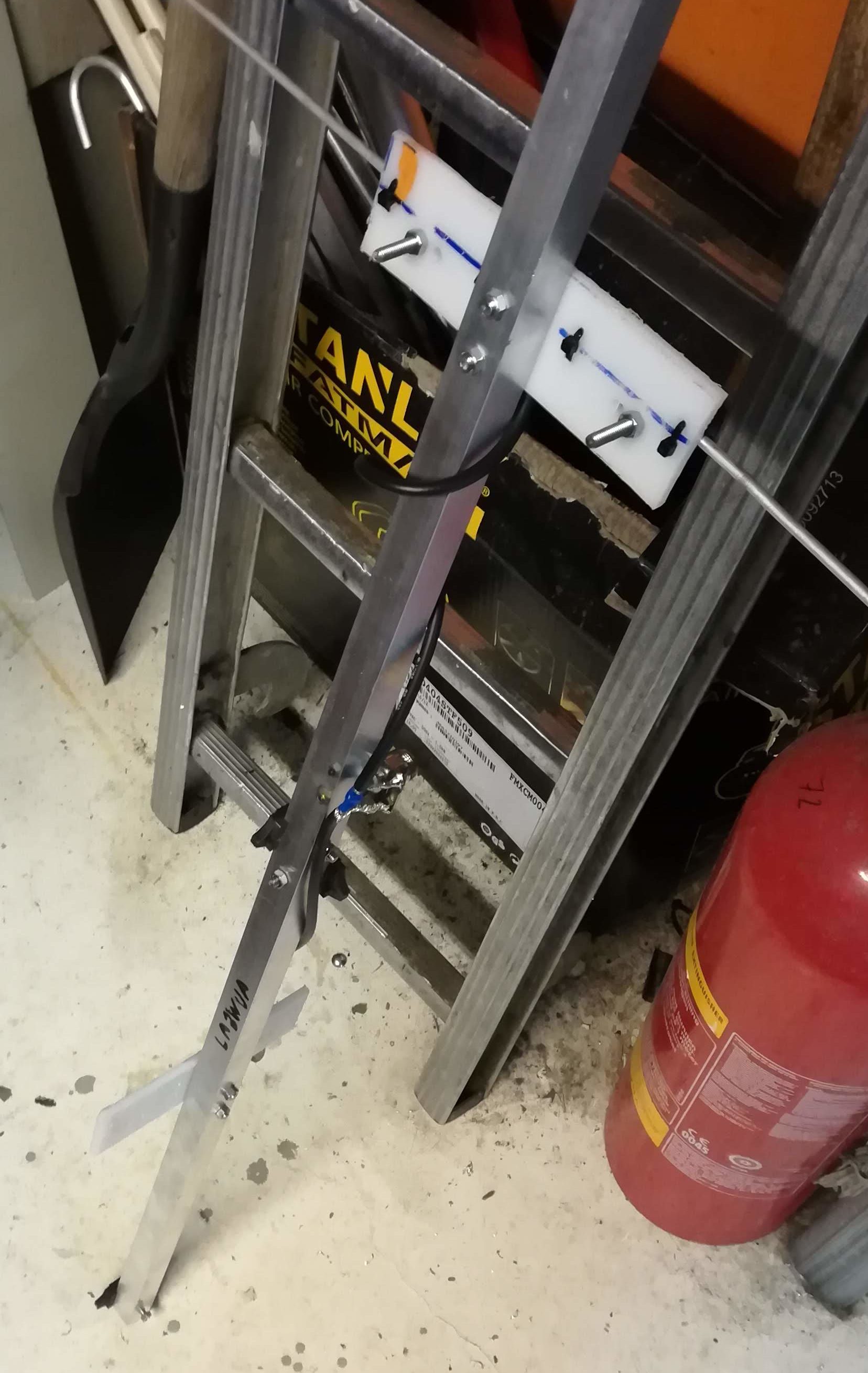
The driven element was mounted and connected. The same procedure was repeated for the other antenna mounted on the same boom.
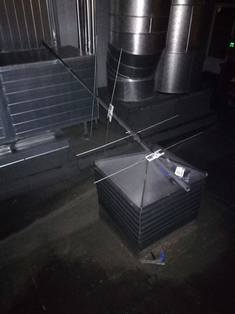
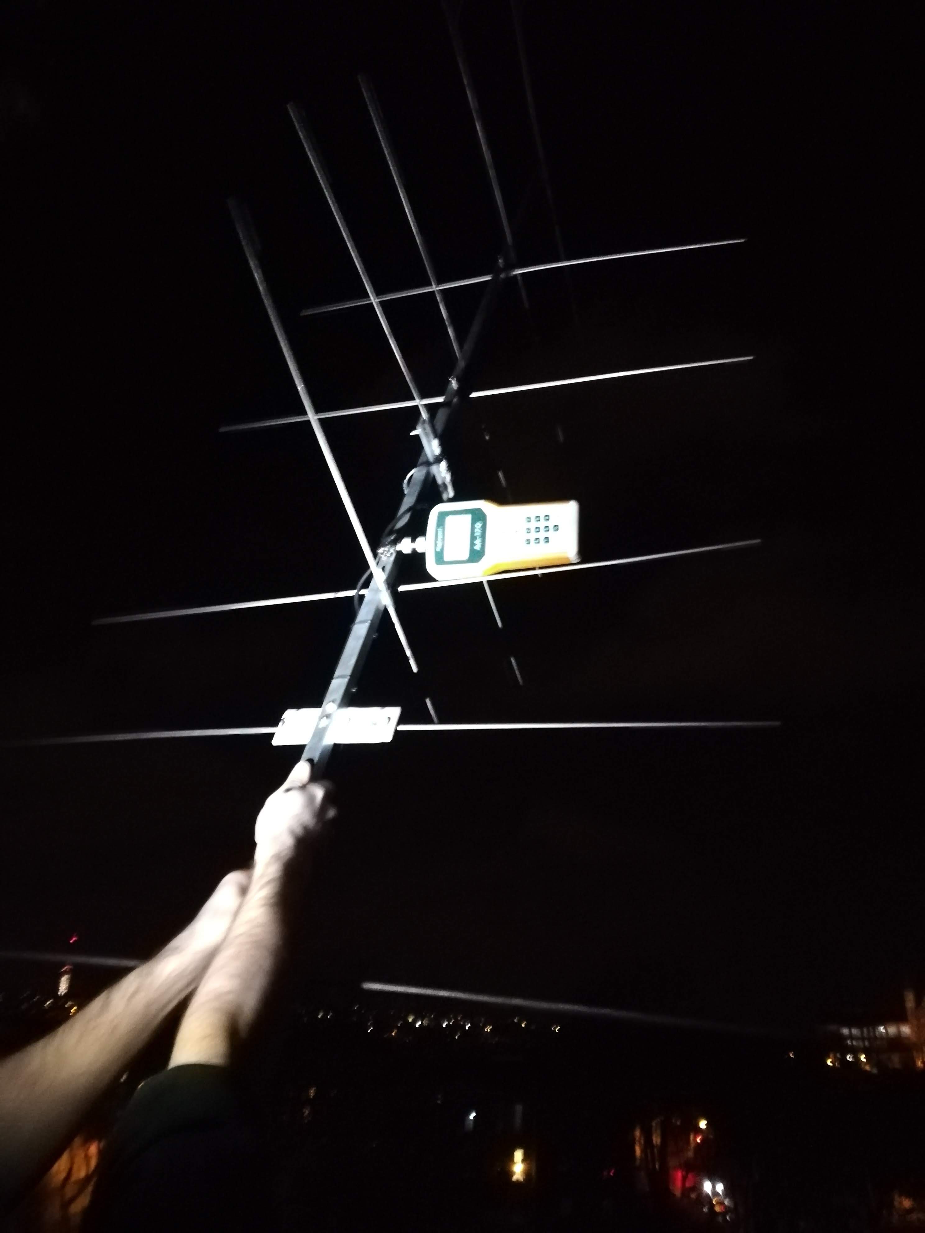
The antenna was taken outside for a bit of fresh air and fixture of its last antenna elements, and final measurements to check whether the antenna was performing according to specifications.
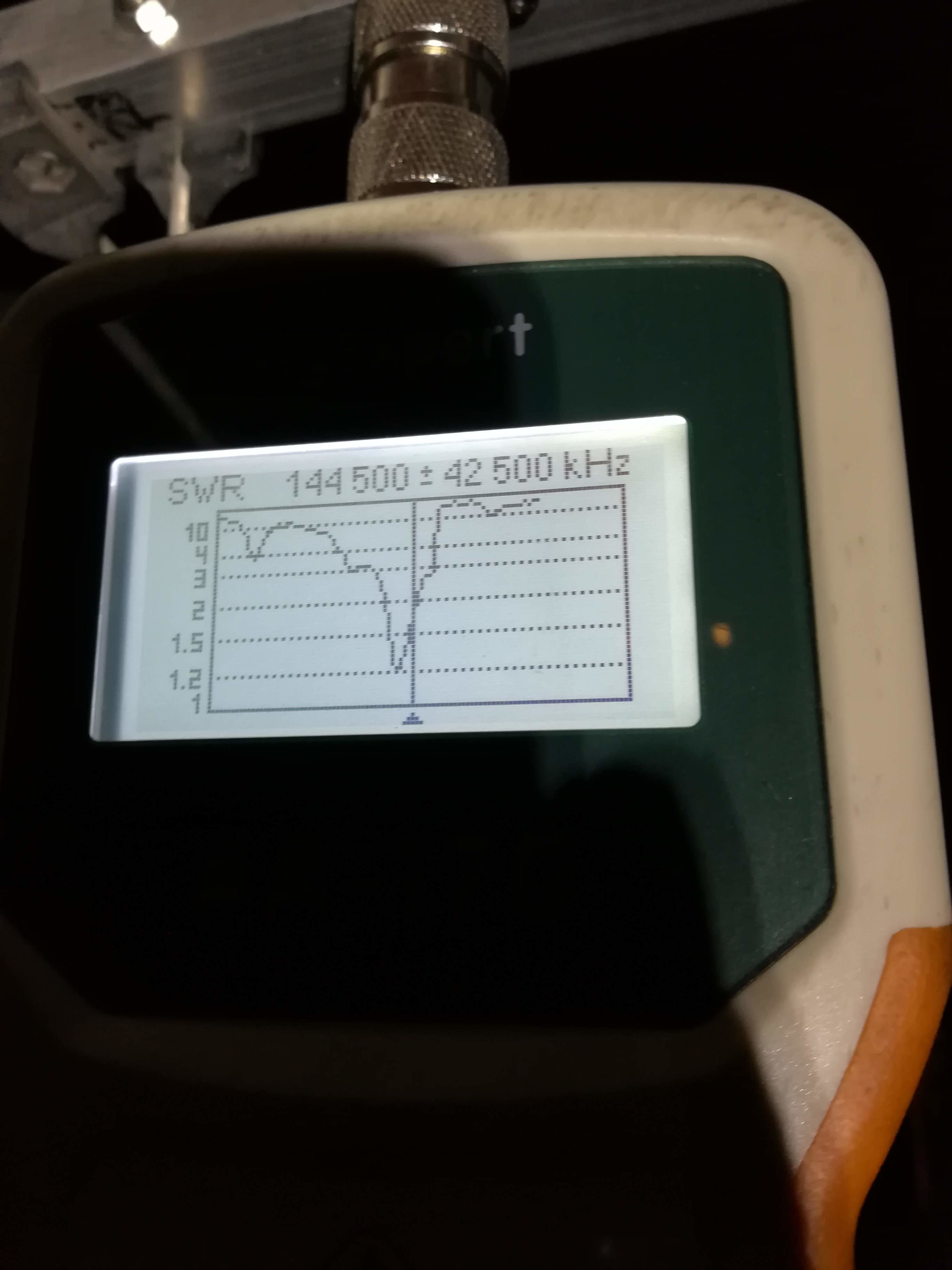
The measurement showed the dip frequency to be slightly off from the target frequency of 144.500 MHz.

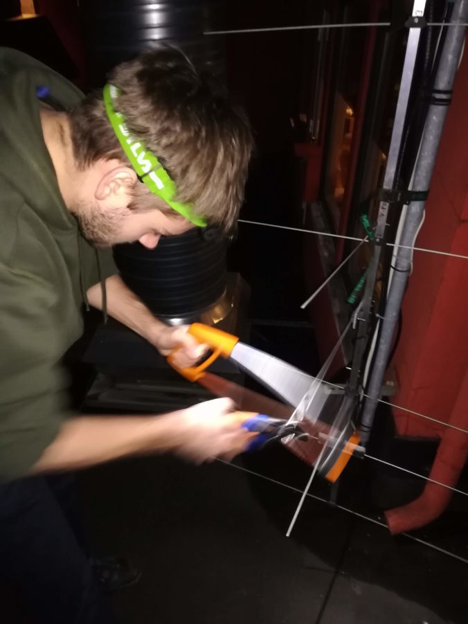
Luckily, excessive violence using a saw against the driven element can shorten it down to a more appropriate length.
Measuring the antenna again…
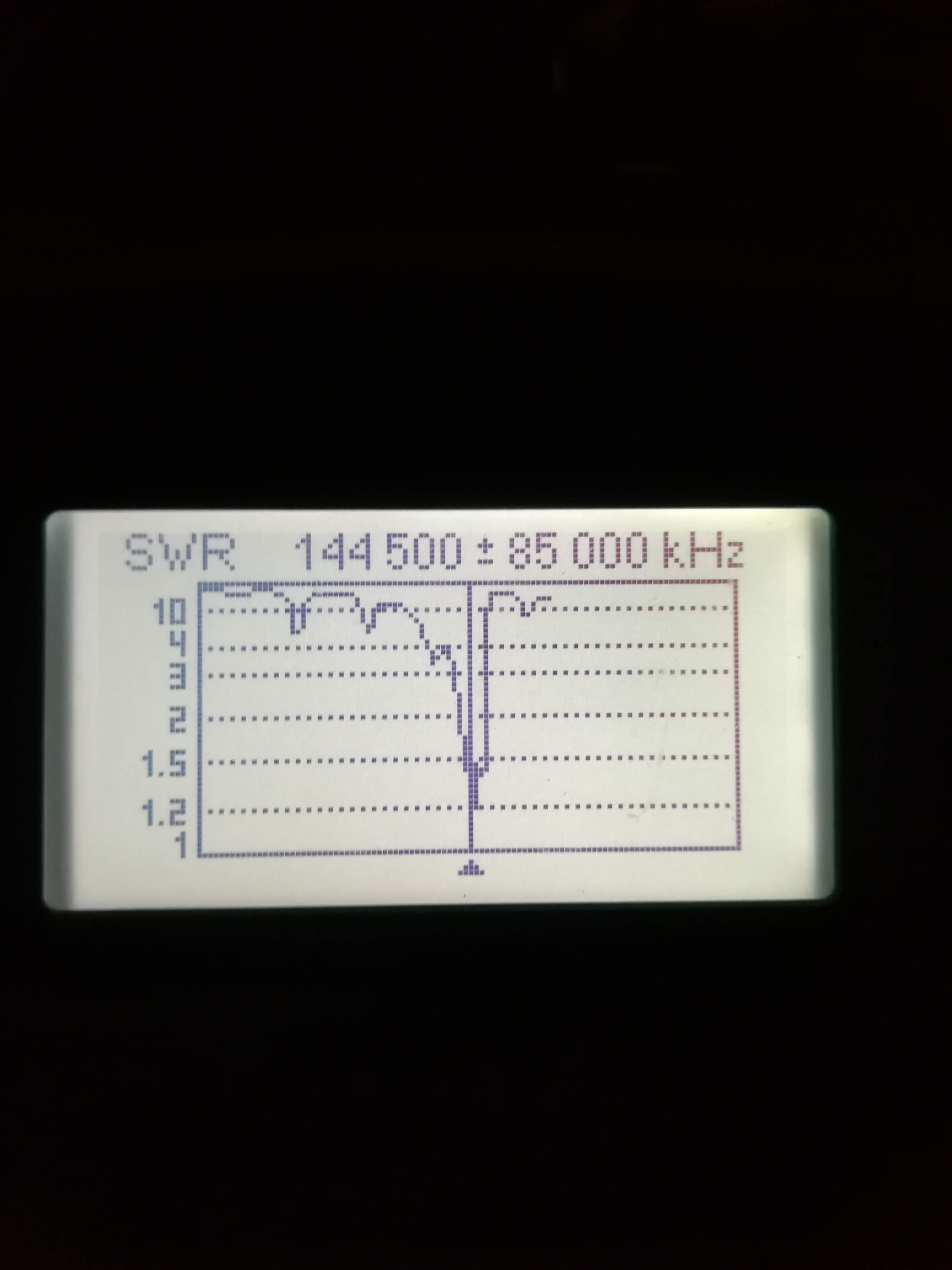
… shows that it has reached the dip frequency to a satisfactory degree. The antenna is finished! Brought to you by engineering genius LA3WUA Øyvind.
We will get back to the rest of the system in a later blog post: fixing the rotor, mounting the rotor, mounting the antenna and stretching both rotor and coaxial cables all the exciting way from the antenna down to the shack. We also have a nice setup for enabling QSOs using our IC9100 radio on the same system, which we’ll fully outline. Stay tuned!


0 Comments
1 Pingback