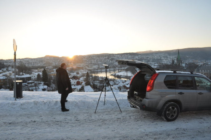
We’ve experienced some discrepancies with the performance of our parabolic dish. During an earlier post, we developed tools for measuring the azimuth-resolved reception power of the dish, and attempted to debug the dish by measuring the reception power of a 23 cm beacon. Unfortunately, we did not have line of sight (LOS) against the beacon, resulting in multipath and fading effects and no clear conclusions on the performance of the system or at which step during the reception chain there could be a problem. The next step was therefore to measure against a signal source with free LOS.
Using a simple dipole antenna and our old TS-2000 rig, we set up a constant signal source at Kristiansten Festning, which is located on a hill close to Samfundet. The antenna at Kristiansten Festning was sequentially oriented in horizontal and vertical directions in order to measure both polarization directions of the dish feed.
-
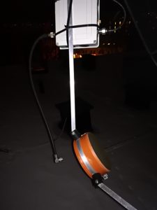
- Five band ring dish feed. Photo: LA3WUA
-
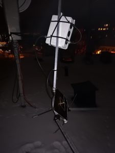
- LA3WUA’s 23cm test feed strapped on top of the ring dish feed mount. Photo: LA3WUA
We had strong suspicions that the point of failure was the five-band ring dish feed installed in the parabola, and LA3WUA therefore constructed a simple 23 cm feed for comparison purposes, which we installed and tested in the same way as the five-band ring dish feed in order to compare the performance of both.
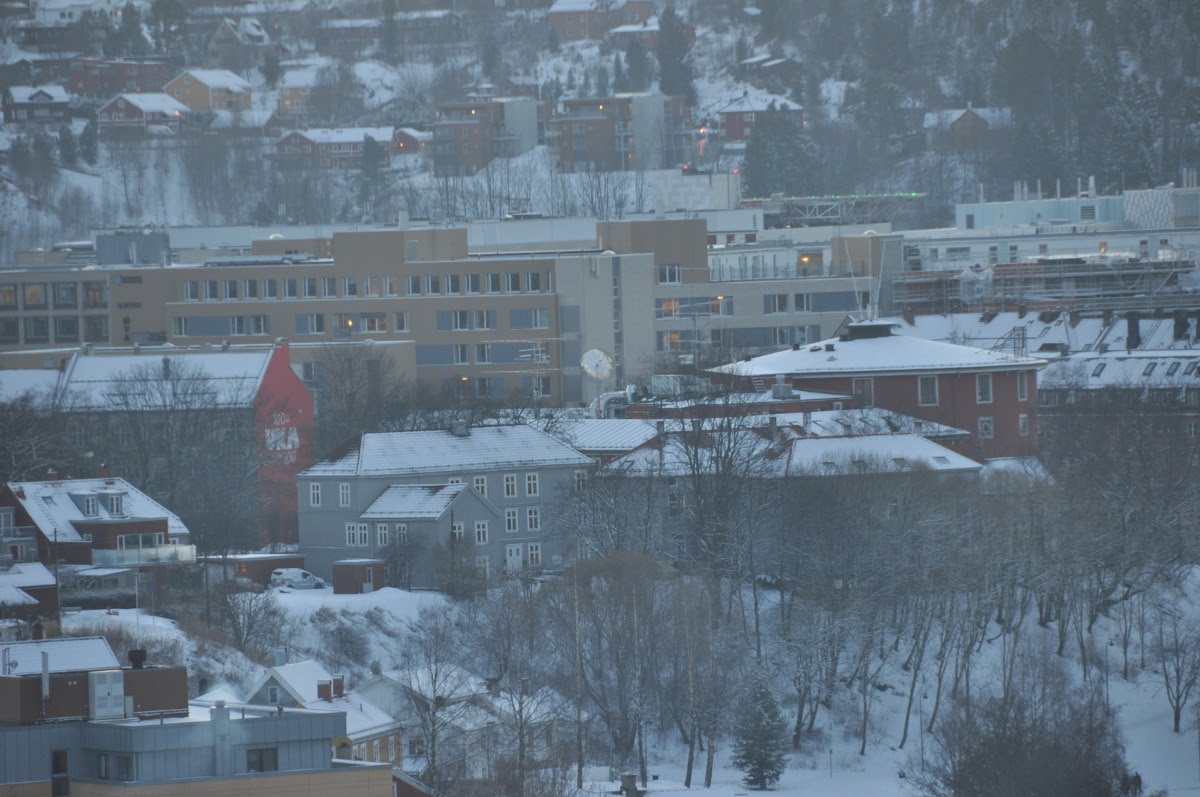
A view from Kristiansten Festning of the parabolic dish during operation, observable in the center of the image. Studentersamfundet can be seen as the round, red building in the center right of the image. Photo: LA3WOA
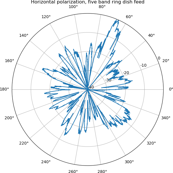
The results from this measurement campaign were very illuminating. Results for five band ring dish feed:
 |
 |
Test feed results:
 |
 |
The patterns are far more clear for free LOS than the earlier measurements done in the last post. It is also starting to get obvious that the problem indeed is with the five band ring dish feed :-). The directivity of the antenna pattern is far better for the test feed than for the original feed, and the signal-to-noise-ratio is higher. The main lobe is approximately 25 dB higher than the sidelobes for the test feed, but only approximately 15 dB higher for the five band ring dish feed. We should actually expect even more power for the test feed (30 dB), but it might be slightly lower due to being off-focus from the focal point of the dish.
Both feeds show major lobes around 320 and 240 azimuth degrees. These can be explained as artifacts due to the surroundings:
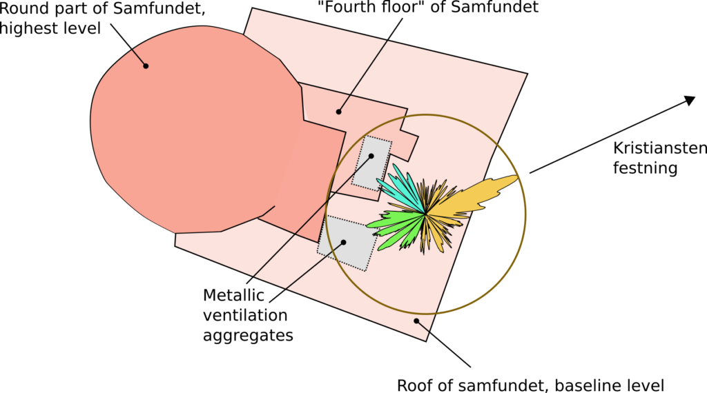
Positioning of the center of the antenna pattern in the approximate location of the parabolic dish, in relation with a rough outline over the Samfundet building (based on satellite photos from google maps and faulty memory). Parts of the antenna pattern we believe are due to reflections against their respective ventilation aggregates are marked with blue and green.
The positions of these lobes are consistent with the locations of large metallic structures that are placed on the roof of Samfundet, and which will reflect the signal from the signal source.
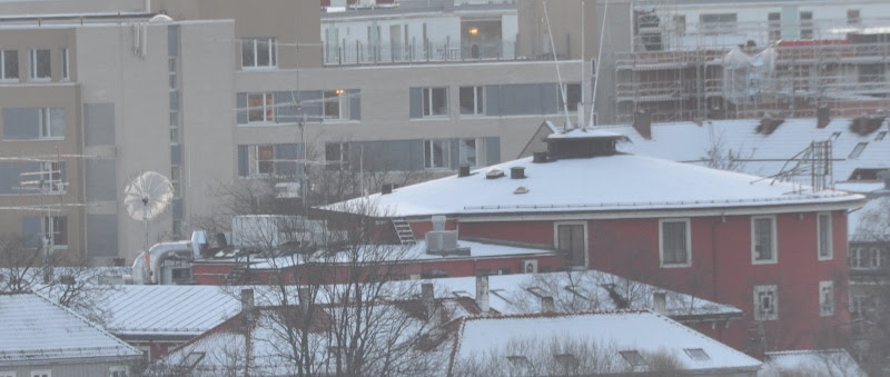
Close-up of the dish and Samfundet. Photo: LA3WOA
The map below shows that the direction of the most prominent part of the pattern is consistent with the general, approximate location of the test source, though some calibration is needed.
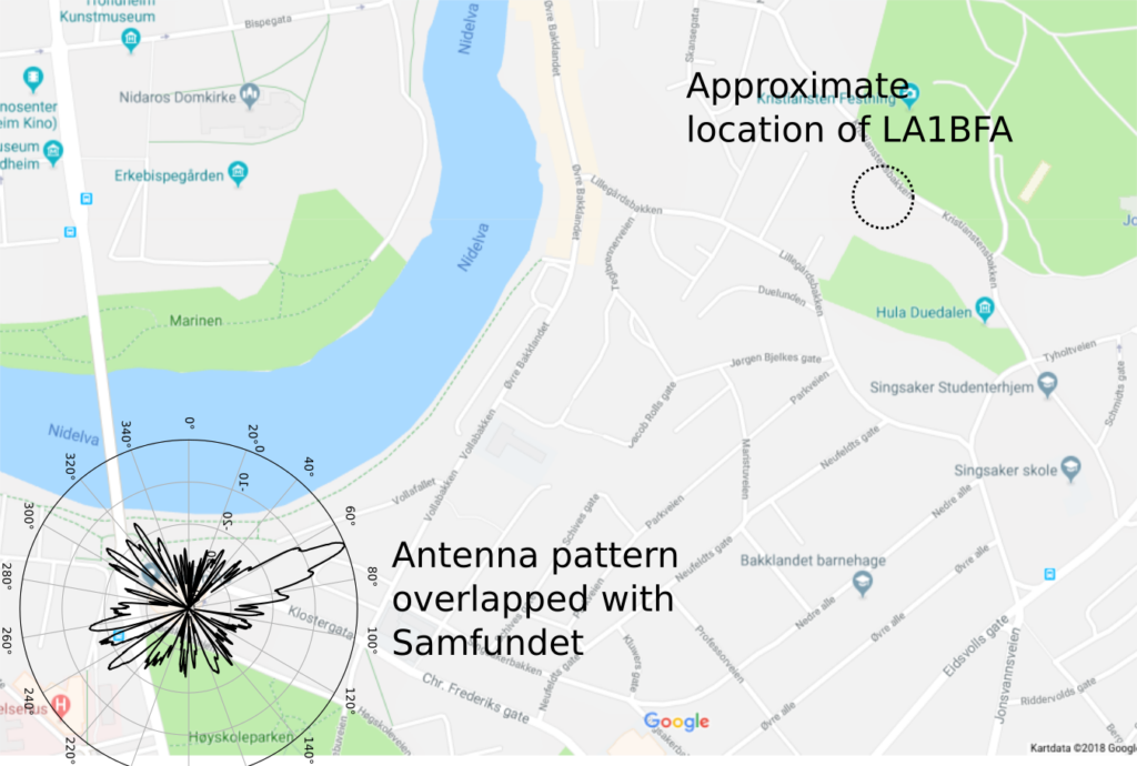
Map obtained from a screenshot of google maps (https://www.google.no/maps/@63.4251556,10.405646,16z?hl=no).
We know now that the there is something wrong with the five-band ring dish feed, and the next step will be to figure out what, and whether it can be fixed.
(Spoiler alert: We’ve actually already opened the box that contains the feed and figured it out, but we’ll wait with the full details until the blog post next week :-).)

0 Comments
5 Pingbacks