ARK has been expanding our antenna park with DK7ZB yagis for 4 m (70 MHz) and 6 m (50 MHz). In order to make the setup more practical we would like to have the antennas selectable via our Microham Double Ten antenna switch. The Double Ten is only specified up to a frequency of 30 MHz, so we wanted to investigate if it would be usable beyond this.
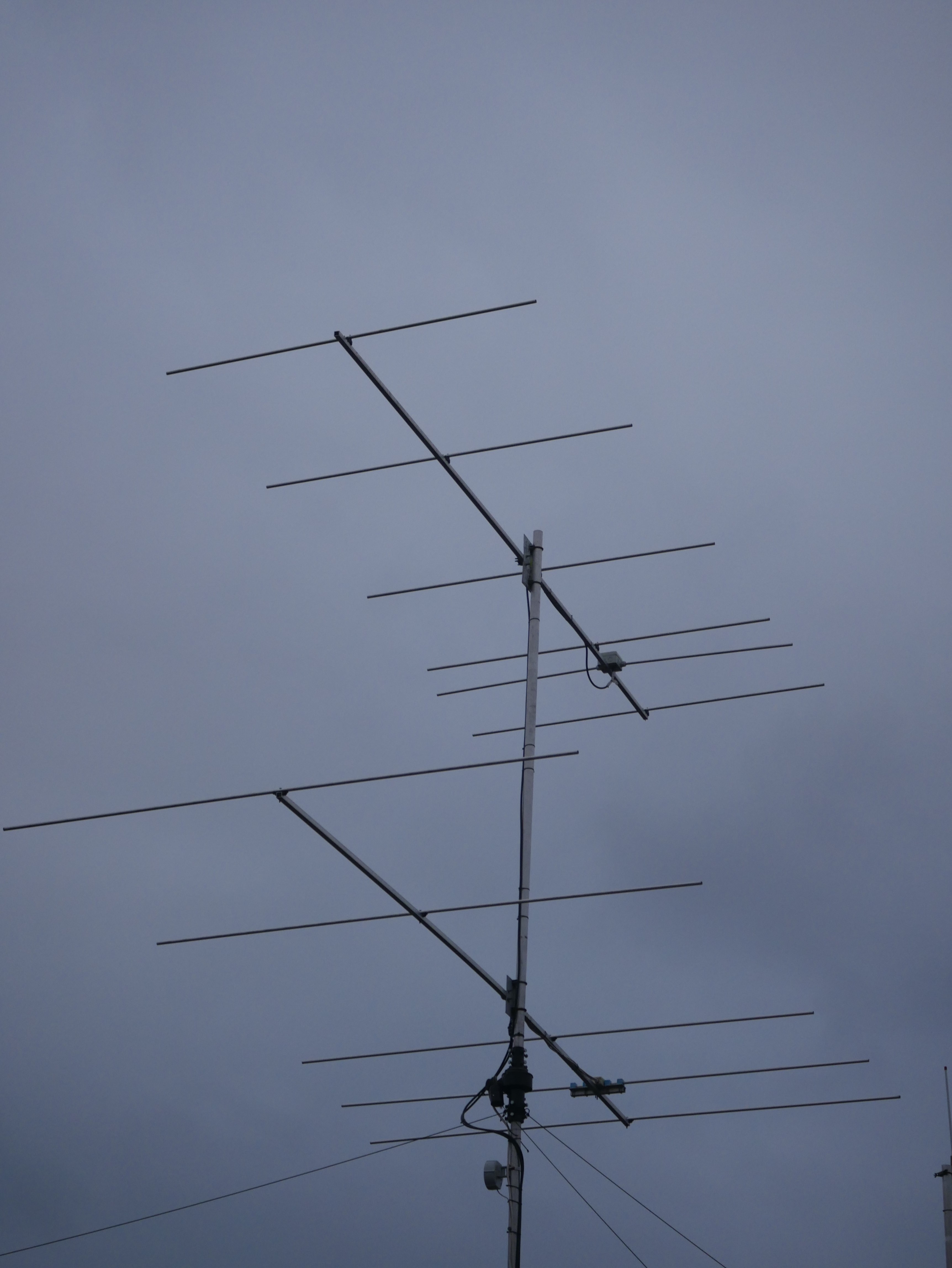
The DK7ZB 6 m (bottom) and 4 m (top) yagis we want to use with the Double Ten switch.
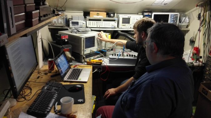
To perform these measurements we used a HP 8753E network analyzer calibrated with a 85052D calibration kit.
Since we are intending to use this device outside its specified frequency range we decided to carefully measure the S-parameters between each output and input port for a sweep from 0 MHz to 200 MHz, focusing on the amateur radio bands covered.
The S-parameters (or scattering-parameters) are a way to measure the response of a RF system by applying a test signal to one port, and assessing the levels that result on the other ports. The results are categorised as S_xy, where S_xy denotes the power that appears at port x from an input on port y. S_xx is also a valid measurement, and gives an indication of how well matched a device is to the target impedance, in this case 50 ohm.
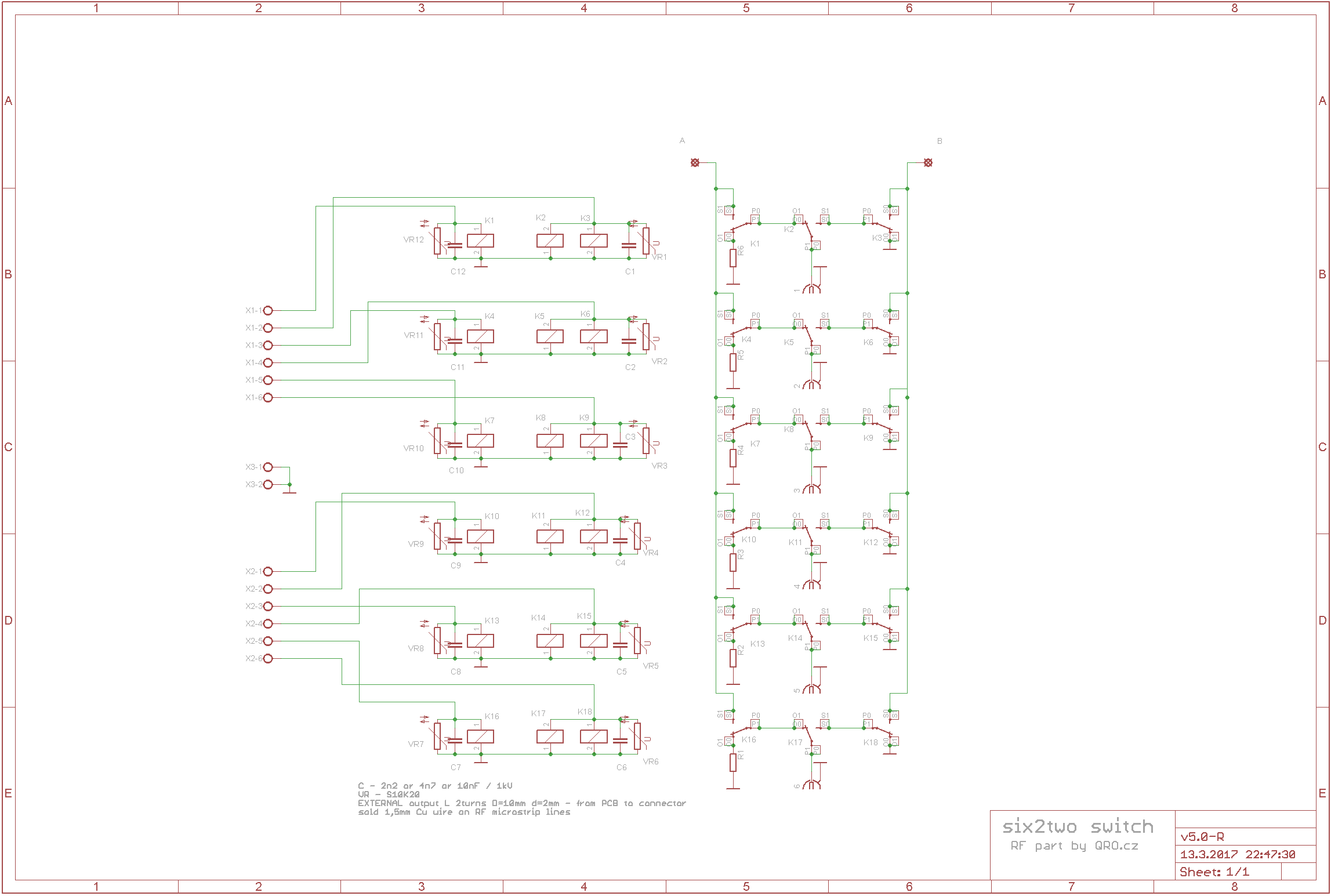
Schematic for a similiar switch, 6 to 2 switch by OK2ZAW. Source: Remoteqth.com
To better understand the internals of the device we wanted to check the circuit schematic, unfortunately none was available from Microham. Luckily OK2ZAW has made an open source 6 to 2 switch, that turns out to be very similar on the inside. Due to substrate and component losses we expect that the antenna ports that are placed further from the radio ports should be have more loss than the ones that are placed closer.
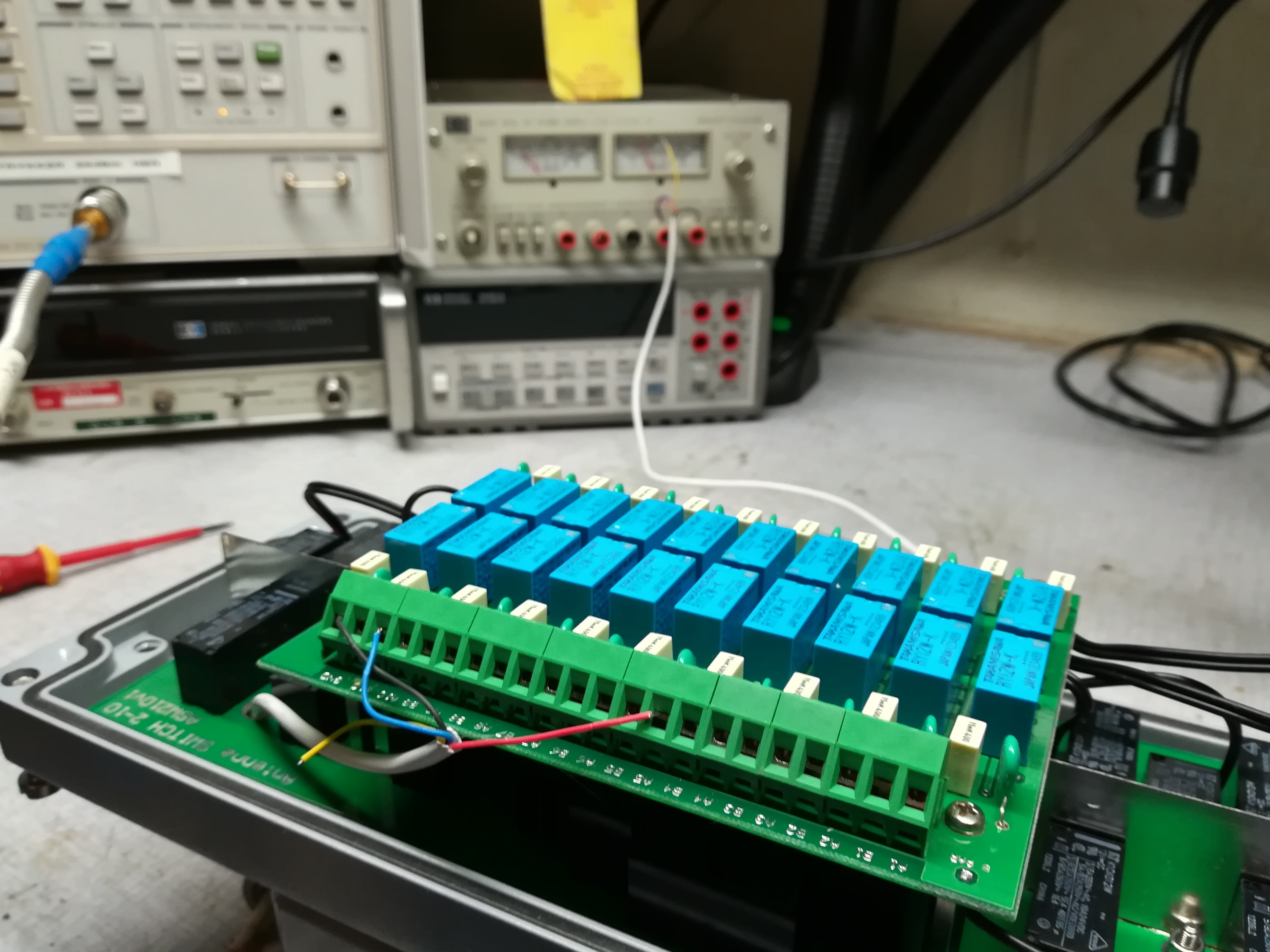
The inside of the Double Ten switch. Wires are attached to a lab power supply to manually select which ports are active/inactive.
To avoid noise interfering with our measurements we took care to re-mount the metal chassis between each change of ports.
Fewer measurements are required if the response between a given port and radio A/B is the same, so this was the first thing we checked.
-
- Insertion loss from Radio A to port 10
-
- Insertion loss from Radio B to port 10
As seen in the figures above the response from port 10 to radio A and radio B are nearly identical. We assume that this is also the case for the other ports.
Insertion loss is a measure of how much signal is lost when translating through a device. For the switch the insertion loss varies quite a bit from port to port. Lowest insertion loss is observed at ports 1 and 10, which are on the edge of the switch. One possible explanation for this is that the edge ports have more series inductance, which could help match the relay better at high frequencies. At port 10 the insertion loss at 70 MHz is only 0.35 dB. This is a promising result, and could indicate that it might be useable for our purposes.
To ensure that the device can operate at 50 MHz and 70 MHz we also need to check that the reflectivity of the input port is not excessively high. Low reflectivity means that the device will translate most of the applied power to the output, and high reflectivity means that a significant portion of the input power is reflected back at the transmitter.
Return loss of port B when output is coupled to port 6
The return loss varies between -8 and -13 dB at 70 MHz, depending on which output is selected. The outputs with lower insertion loss have better match. A return loss of -13 dB corresponds to a SWR of ~1.6. At the antenna port we are not so concerned about the reflectivity, as the power levels are not a cause of concern when receiving.
The final characteristic that is investigated is the isolation between Radio A and Radio B ports. If two transceivers are operating on the switch simultaneously, the isolation between the ports must be sufficiently high to ensure that either radio is not saturated when the other transmits.
Isolation between Radio A and Radio B ports.
The isolation between ports is not very high. When transmitting with 100 W at 70 MHz, 2 mW will be coupled to the other radio. This can cause the receiver to saturate if the filtering is not sufficient. Typically the antenna will receive signals that are on the order of pWs, so the receiver would need tremendous dynamic range in order to cope with 2 mW coupled.
Practically this is not a large problem, as we don’t intend to use two radios at 4 m simultaneously. Furthermore, 70 MHz is heavily attenuated by the preselectors filters that are common in HF transceivers, so the intermediate frequency stages are likely to be sufficiently shielded from saturation.
At low frequencies (>30 MHz) the measurement is seen to be noise floor limited.
In conclusion, given that port 1 or 10 is used, the Double Ten will work well at 6 m, and decently at 4 m. Care should be taken to not run excessive power at these frequencies, atleast not without extra filtering on the other radio ports.
Thank you to LA1BFA for providing a Double Ten switch for testing! It was very convenient to not have to disassemble the one we already have installed.

Leave a Reply