ARK is making an open source ground station that is compatible with GENSO and SatNOGS. We want to focus on documentation, making it easy for others to adopt.
We are attempting to approach this problem from a radio system perspective. We want to give a guideline to set up a modular distributed network node. The node should support common ham activities in the bands covered, such as EME and satellite work.
The ground station will cover 1 to 10 GHz and be RX and TX capable.
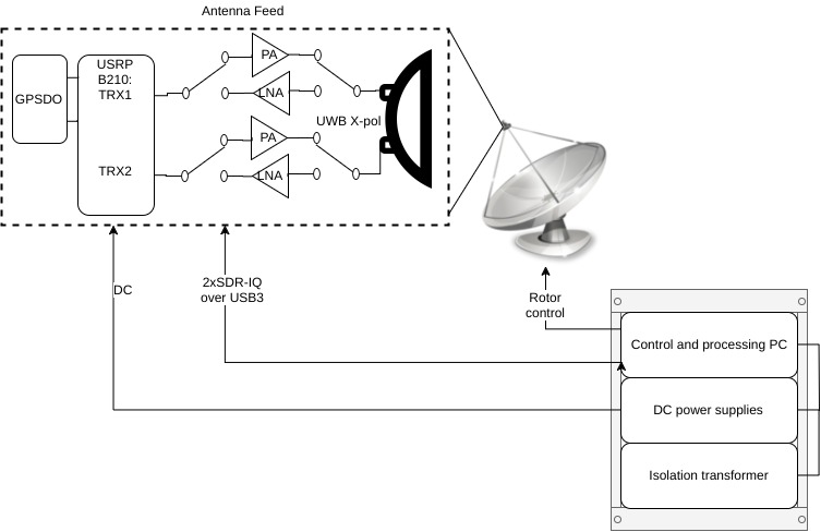
Block schematic of the project
The reference ground station will support up- and downlink covering 1 to 10 GHz using a cross-polarised dish feed. A dual channel software defined radio is used as the central transceiver, allowing for a wide range of applications to be programmed on the fly.
By using two radio channels and two polarisations we want to control polarisation schemes dynamically in software. This will allow for optimization of a large range of satellites. Using this setup we aim for access to linear vertical and horizontal, right and left handed circular as well as some elliptical polarisations.
This ground station (and network) could be interesting for amateur radio groups, CubeSat initiatives and research projects.
The Antenna(s)
We are going to use a parabolic dish antenna with around 30 to 45 dBi gain, increasing with frequency. The parabolic dish will be a 3 m kit by rfhamdesign. In the long run we might attempt a custom parabole design that aims to lower costs even further, utilizing machined or 3D-printed parts and metallic mesh.
At the core of the project at this stage is the choice of feed antenna for the dish. We want a feed that has the following attributes:
Continuous coverage over 1 to 10 GHz, S11 < -10 dB: Covering the ham bands from 23 cm to 3 cm. There are also a lot of interesting satellites in these frequencies.
Stable phase center over the frequency range: The phase center is the apparent center of radiation, for a feed antenna this is particularly important as it decides where the antenna should be placed in relation to the dish. If the phase center shifts with frequency the main lobe of the antenna will also change with frequency, making calibration and gain optimization hard.
Constant antenna pattern over the frequency range: Similarly to the previous requirement it is desireable to have a stable main lobe. Distance to the dish, as well as a backwards ground plane will have to be considered.
100 W power handling: In Norway this is the legal limit output power for the bands 23 cm to 3 cm.
Dual linear or dual circular polarisation: By having either of these combinations it is possible to combine the remaining polarisations as well as a set of elliptical polarisations.
We are looking into several antenna topologies. Luckily there’s a lot of research available for ultra wideband (UWB) dish feeds, as they are very common in radio astronomy. Our design differs a bit from these however, since we also intend to use the antenna for transmit applications. The main difference is the power handling, as radio astronomy applications usually are RX only.
So far we have found two promising designs, and are running simulations to get the exact dimensions.
Dual linear spiral antenna
The first of the two is the dual linear spiral antenna. This is a planar antenna that is realizable on printed circuit boards. For additional power handling machining the elements may be a better choice. For high frequencies the antenna has to be scaled in a way that leads to lots of tight gaps between metallic elements, for high power levels this will cause spark-gaps, and the antenna will not function as intended.

Dual linear spiral antenna
Dual ridge vivaldi antenna, alternately called quad ridge horn antenna:
The more promising of the two designs is the horn antenna, as several commercial designs that fit our specification already exist. One such design by Schwarzbeck Mess-Elekronik is shown in a picture below. This antenna covers 0.4 to 10.5 GHz with an efficiency of 90% or better. It also handles 200 W.
We are looking forward to learn more about the design as we progress with our own.
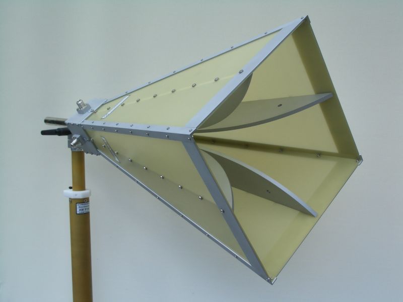
A dual polarised horn by Schwarzbeck Mess-Elektronik
Getting funding
The other thing that we have been working with at this stage is getting funding for development. Transistor costs alone are so high that we couldn’t do this on our own.
We would like to give a big thanks to NTNU IES, KSAT, Marlink, Sit, Radionor, Jotron and Kongsberg for making this happen!
What’s next?
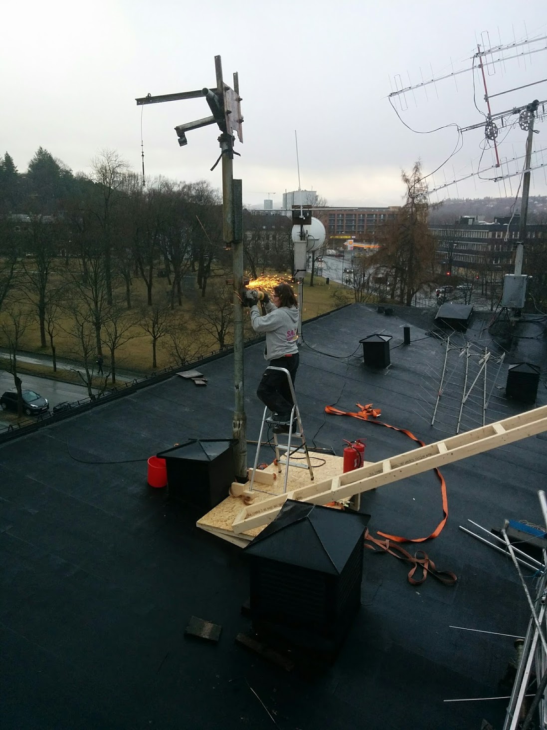
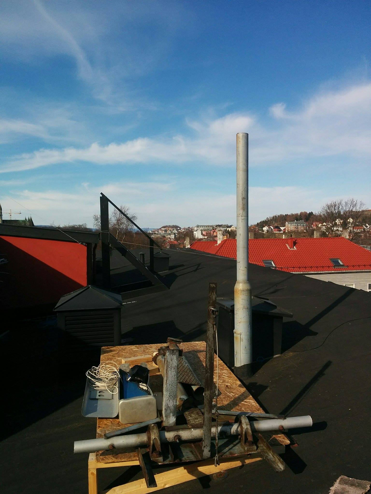
We have prepared a lamp post mast that will serve as an attachment point for a tiltable mast, which LA2USA is designing. The lamp post previously housed ARKs 5.5m spoil in the early 90s, seen in the photo below.
The story of the old spoil ended with a winter storm, which is why we’re making some changes to the mast. Hopefully by tilting it down during windy periods it will catch less of the harsh winds. This also comes with the benefit of easier maintenance since the feed will be more accessible.
We have also ordered a rotor and 3 m mesh parabole kit from rfhamdesign. Building will commence when parabole kit and the LA2USA mast arrive here mid June.
As the design on LNA, PA, antennas and software continues there will be more updates.

0 Comments
3 Pingbacks