I have a quite long Aircell 7 cable that I would like to know the length of, but didn’t want to uncoil. This is a good opportunity to showcase a technique for measuring the length and attenuation of a coaxial cable, using a function generator and an oscilloscope.

Fig 1: Time delay for RG58 patch cable
Measurement background
Using a function generator in burst mode we can measure the reflection from the open end of a coaxial cable. An oscilloscope is connected through a t-junction between the function generator and the test cable. Since the internal resistance of the oscilloscope is high, and current prefers the path of least resistance, and the burst signal will travel to the coaxial cable. A small amount of the signal will coupled to the oscilloscope. We denote this as the incident voltage, Ui .
Upon reaching the open end of the cable, the wave will reflect and travel back towards the function generator. As the wave passes the oscilloscope a small amount will be coupled. We denote this as the reflected voltage, Ur. The reflected wave finally dissipates when it reaches the function generator.
This is very similar to tying a rope to a pole, swinging it and having the rope reflect back.
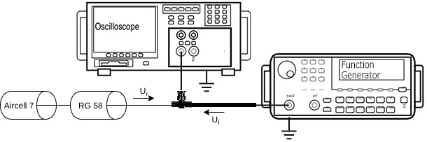
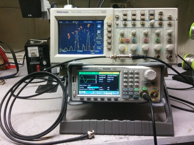
Fig 2: Measurement setup
The time difference between Ui and Ur is the time it takes for the wave to propagate to the open end of the coax and back again. Using this we can calculate the length of the coaxial cable using the following formula:
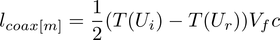
Vf is the velocity factor of the coaxial cable and c is the speed of light. Since the time between incident and reflected is the round-trip time we divide the result by two.
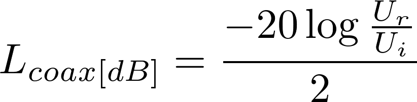
By seeing how much the voltage has dropped on the reflected wave relative to the incident wave we can calculate how much loss the coax has at generator frequency. Since the reflected wave passes through the cable twice we should divide by two to find the one-way attenuation.
Some measurements
As mentioned, I have quite long Aircell 7 cable that I would like to know the length of, but didn’t want to uncoil. To keep everything neat I used a short RG58 cable to patch it together. This is the setup shown in figure 2.
The two cables are made using different dielectrics, and will have different velocity factors. Aircell 7 has a Vf of 0.83, RG58 has a Vf of 0.66. To account for this we should first measure the delay and attenuation caused by the RG58, and then subtract that contribution from the Aircell 7 measurement.
To be able to measure on the short RG58 cable I am using a 1 cycle 100 MHz sine wave burst. The burst is set up to repeat every second, this means that any remaining oscillations should have fully died out. A generator frequency of 10 MHz is sufficient to get accurate results, but only if the cable you are measuring is longer than 20 m.
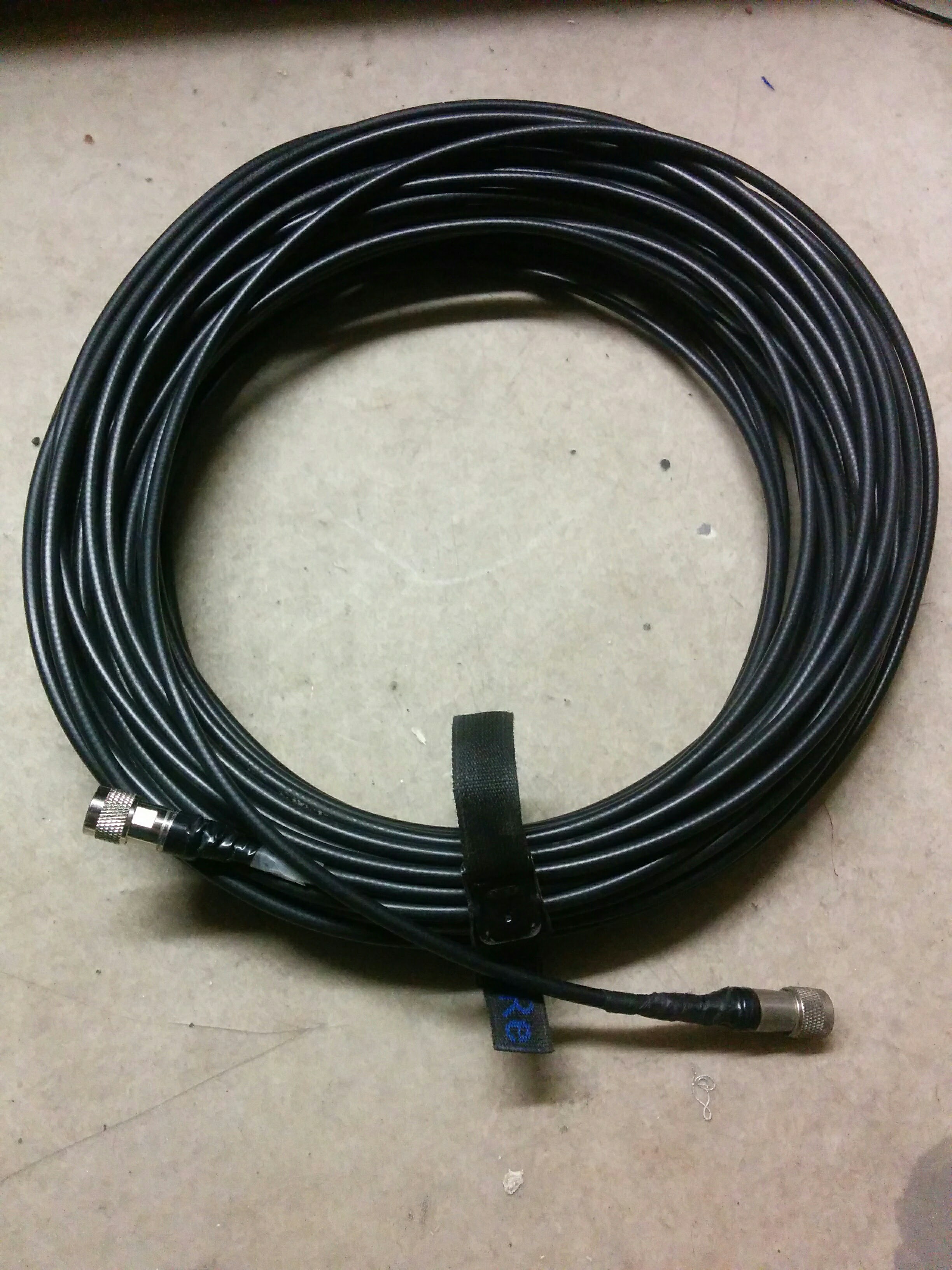
Fig 3: Unknown length Aircell 7

Fig 4: Voltage drop of RG58 patch
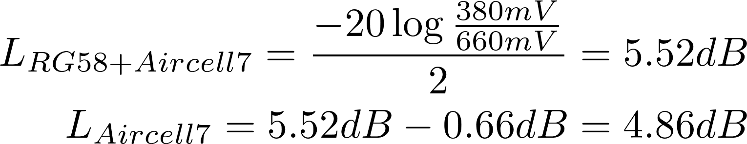
Figures 1 and 4 show the measurement results from the RG58 patch, we put the results into the formula and get the following results:
![]()
I also measured the RG58 coax with a measuring tape, and found the physical length to be 1.55 m.
![]()
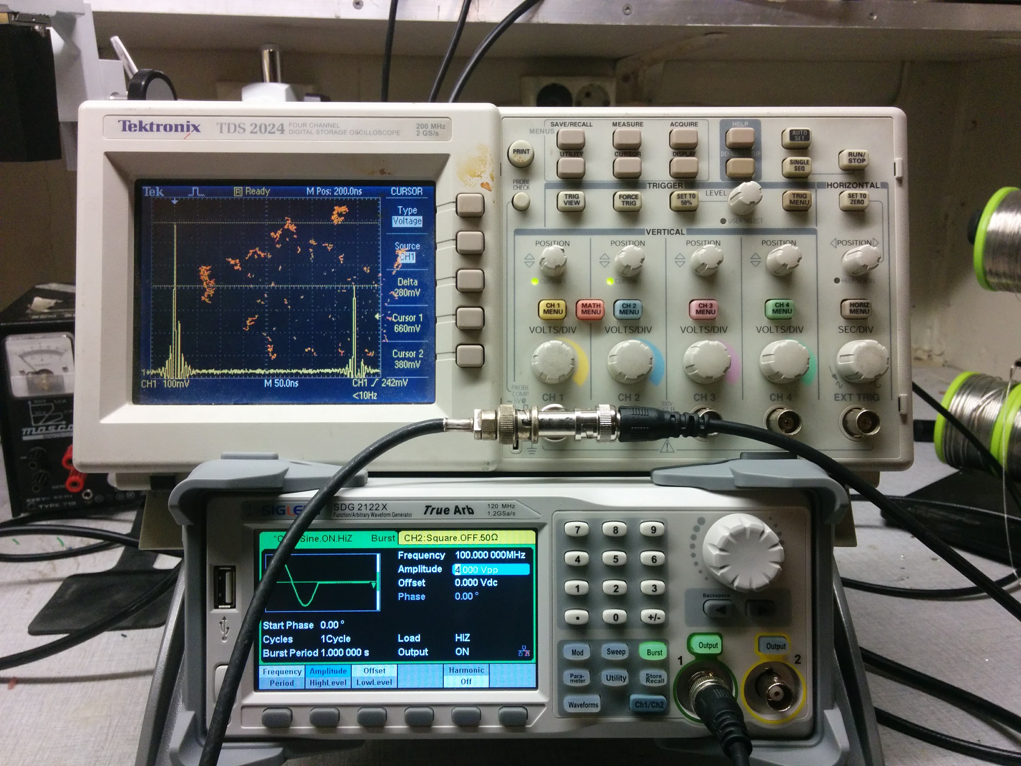
Fig 5: Voltage drop Aircell 7
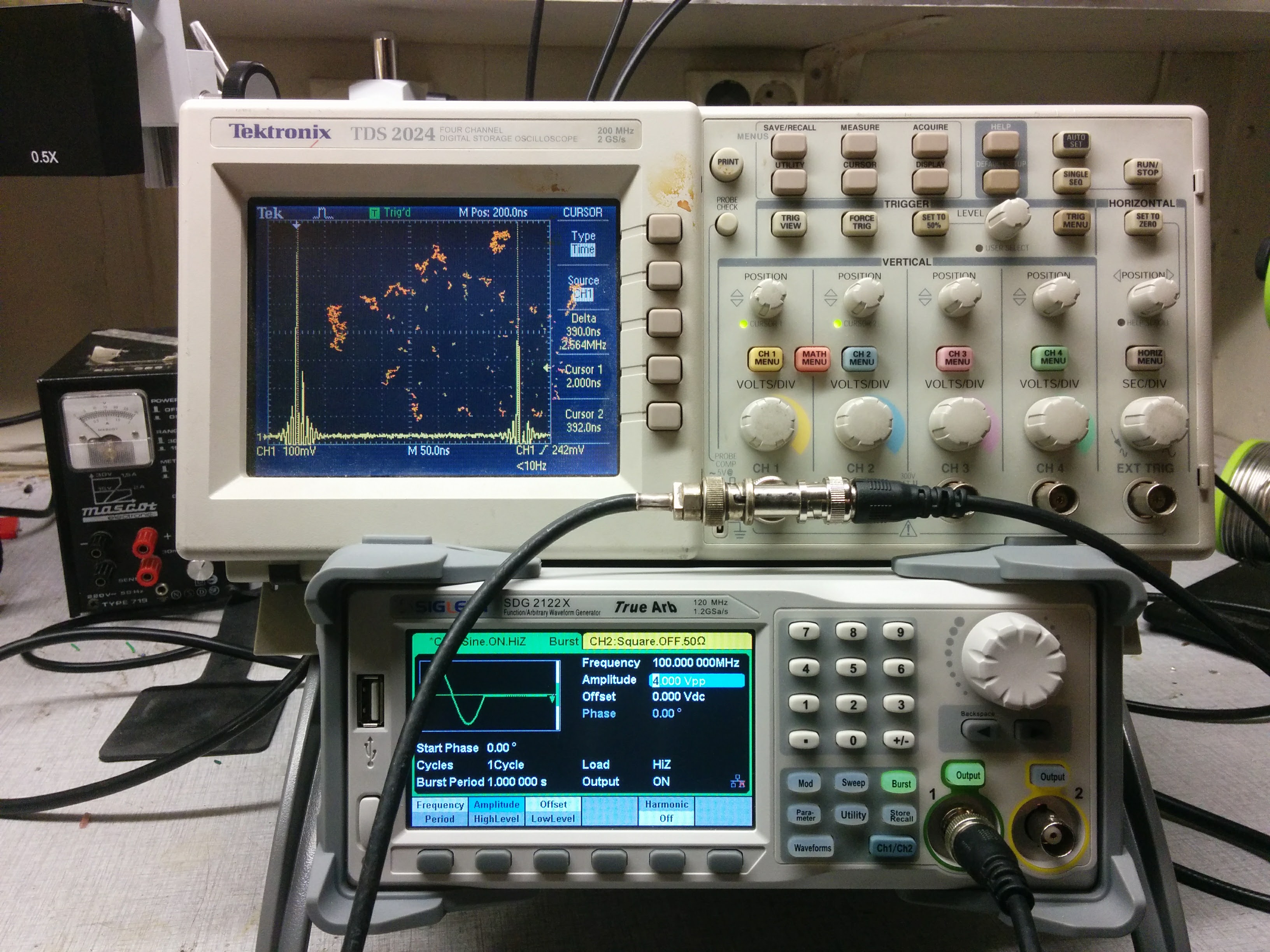
Fig 6: Time delay Aircell 7
Finally using the results from figures 5 and 6 we find the length and attenuation of the Aircell 7 cable
![]()
In conclusion this method is a quick and efficient way to measure the loss and length of a coaxial cable. If you have a broken cable the breakage point will also reflect, so this can be a very useful tool to pinpoint where you need to mend the cable.
It should also be said that the accuracy of this method depends largely on the accuracy of the velocity factor given in manufacturer specifications, meter order deviations can easily arise from a wrong spec. The influence of the oscilloscope could also matter, some people connect 10X or 100X probes to the t-junction for these measurements, I found it to be fine using just the internal impedance.

Leave a Reply